


21
1
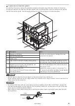
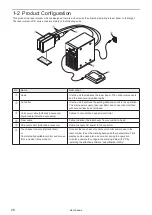
Internal shutter
This is a shutter inside the head. The emission of laser beam is stopped by closing the
internal shutter.
2
Laser radiation indicator
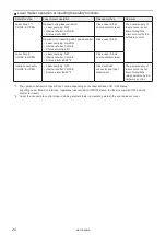
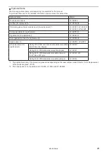
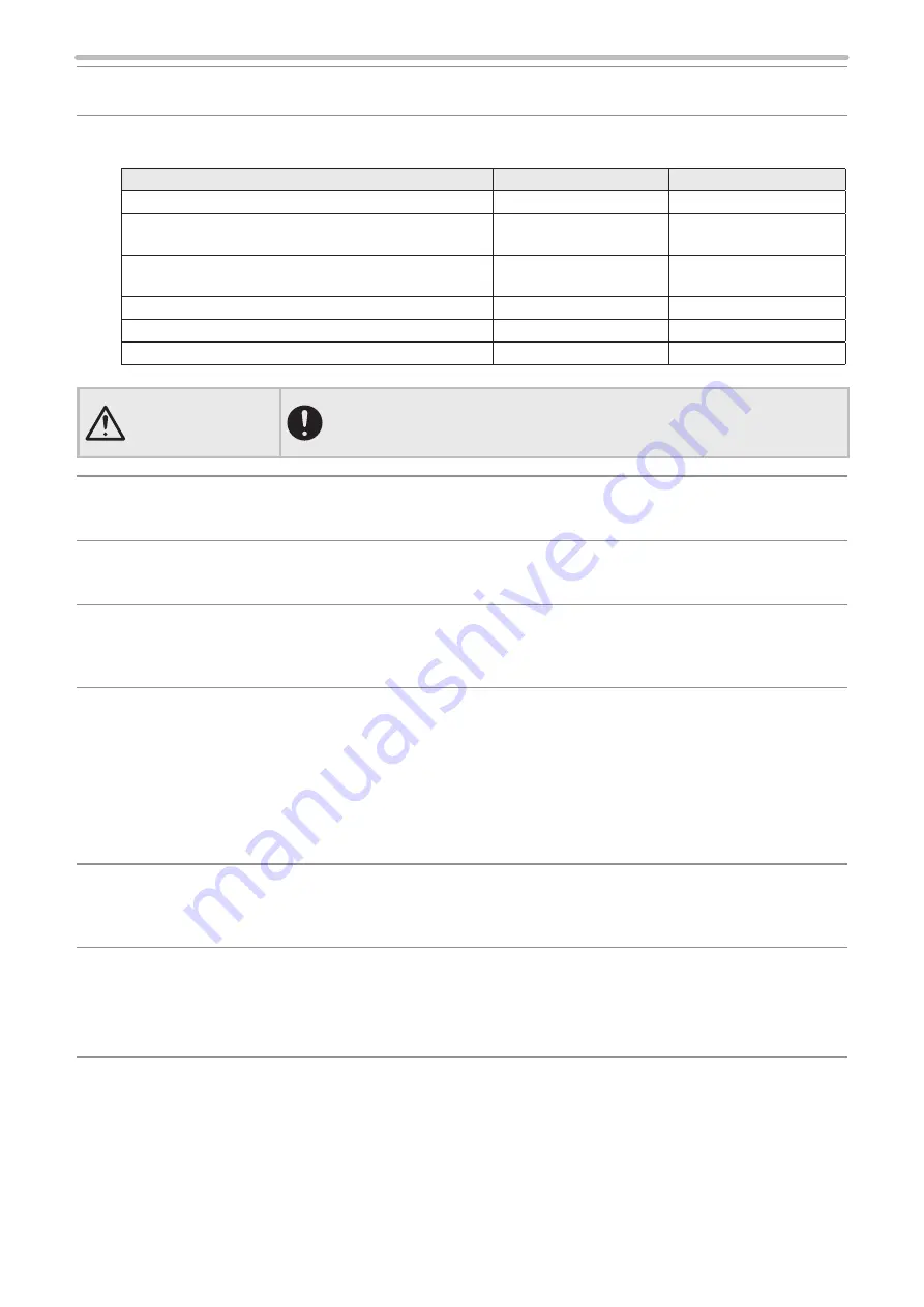
The operations of the laser radiation indicator are as follows:
Laser marker status
Head indicator
Controller indicator
Non-laser pumping
Lights-out
Lights-out
Laser pumping is in progress (uncompleted) and shutter
closed
White flashing
Lights-out
Laser pumping is in progress (uncompleted) and shutter
opened
Green flashing
Lights-out
Laser pumping is completed and shutter closed
White lighted-up
Lights-out
Laser pumping is completed and shutter opened
Green lighted-up
Lights-out
Being in laser emitting
Orange lighted-up
Orange lighted-up
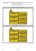
WARNING
• If the laser radiation indicator is placed out of the sight of operators, place the
external indicator light or warning lamp on the immediately apparent place on
the system.
3
Key switch
The key switch is used for the system power ON/OFF.
To prevent the unauthorized operation, the system key should be in safekeeping by a
laser safety manager.
4
Alarm reset switch
This switch is used to reset the system when an alarm generates. LED lights up in blue
when an alarm generates.
Release the cause of alarm and press this switch.
5
This switch is equipped in the front side of the controller.
Push the switch at emergency to stop the laser radiation immediately.
The laser pumping is stopped forcibly and laser radiation stops.
Turn the switch to the direction of the arrow to release it.
6
Laser stop input
(Input terminal)
The input terminal equips Laser Stop signal.
Opening either of the signals disables the laser emission as follows. Construct the
safety system by connecting it to the door or switch of the equipment.
• Operation when laser stop 1 is released:
When laser is not radiating: The internal shutter is closed.
When laser is radiating: The internal shutter is closed and laser pumping turns off.
• Operation when laser stop 2 is released:
The internal shutter is closed and laser pumping turns off.
Refer to “3-3-3 Signals on input/output terminal” (P.89) for details.
7
Input/output terminal
The terminal equips various signals, such as shutter input, marking output, mark end
output, ready output etc.
Use these signals for the purpose of controlling other external safety devices, such as
an indicating lamp.
8
Interlock connector
9
Interlock connector2 *2
This connector is used to construct the interlock system to stop laser pumping and
radiation. Opening this connector makes laser pumping and radiation to stop forcibly.
Refer to “Construction of interlock system” (P.25) for details.
For LP-Sxxx-SF/LP-Sxxx-LS1 type, using Interlock 1 , 2 and a safety relay unit, the
safety designed system with the double-circuit of the interlock can be constructed.
*1 : Not equipped on LP-Sxxx-LS1 type.
*2 : Equipped only on LP-Sxxx-SF/LP-Sxxx-LS1 type.
ME-LPS-SSM-8
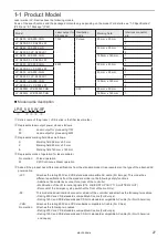
Summary of Contents for LP-S Series
Page 15: ...15 MEMO ME LPS SSM 8 ...
Page 26: ...26 Chapter 1 Specification ME LPS SSM 8 ...
Page 41: ...41 Chapter 2 Preparation ME LPS SSM 8 ...
Page 78: ...Chapter 3 Connection for External Control ME LPS SSM 8 ...
Page 126: ...Chapter 4 Maintenance ME LPS SSM 8 ...
Page 148: ...Troubleshooting ME LPS SSM 8 ...
Page 169: ...Index ME LPS SSM 8 ...
Page 172: ...172 MEMO No 9000 0066 16V ME LPS SSM 8 ...
Page 173: ...No 9000 0066 16V ...


