


25
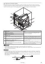
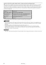
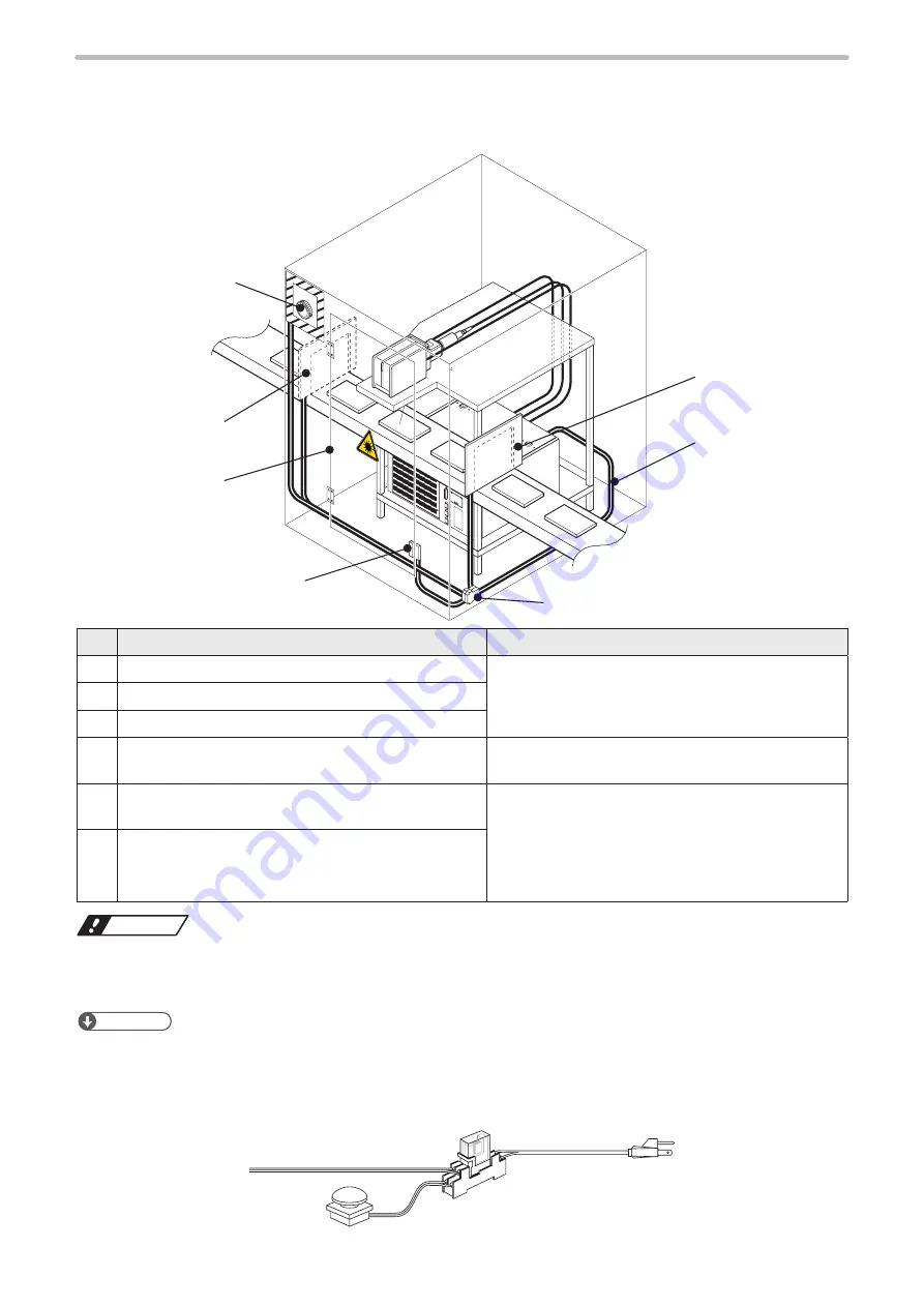
Construction of interlock system
For operating this product, construct the protective enclosure enclosing the range of the laser radiation for protecting
the exposure caused by the reflection of the laser radiation from the marking object or the surrounding objects, and also
construct the interlock system. The following figure shows the construction sample of the interlock system.
ABCD
ABCD
ABCD
BCD
Stop
q
w
r
e
y
r
t
No. Description
Note
q
Emergency stop button
Construct a control system for shutting off the laser
power when it is opened.
w
Door for the maintenance
e
Safety switch
r
Laser protection shutter for marking object gateway
Construct a control system which will separate (cut off)
the laser beam or shut off the laser power when it is open.
t
Depending on the system control specification, use
safety relay unit or safety PLC etc.
Connect the input signals of the interlock connector to
the devices
q
to
r
.
Besides the interlock connector, to the devices
q
to
r
can also be connected input/output terminal signals
depending on the control specifications.
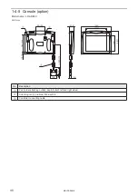
y
To the interlock connector
For LP-Sxxx-SF/LP-Sxxx-LS1 type, use the double
interlock connectors.
ワㄐㄕㄊㄆ
• Interlock input is connected to the operating coil of the internal relay in the controller unit.
Connect interlock inputs with the non-voltage contact (dry contact) such as a relay or a switch. Do not connect with the
voltage contact such as a transistor.
ンㄆㄇㄆㄓㄆㄏㄆ
• For LP-Sxxx-SF/LP-Sxxx-LS1 type, when making a system compatible to ISO 11553-1 / ISO 13849-1, construct the
redundant interlock system by using interlock 1 and 2 connected to safety PLC or safety relay unit to shut off the laser
power supply in accordance with the standards.
• When primary AC power supply of the system is performed as a safety measure, process AC power cable to set the
switch as follows.
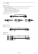
Cable
Switch
Relay
ME-LPS-SSM-8
Summary of Contents for LP-S Series
Page 15: ...15 MEMO ME LPS SSM 8 ...
Page 26: ...26 Chapter 1 Specification ME LPS SSM 8 ...
Page 41: ...41 Chapter 2 Preparation ME LPS SSM 8 ...
Page 78: ...Chapter 3 Connection for External Control ME LPS SSM 8 ...
Page 126: ...Chapter 4 Maintenance ME LPS SSM 8 ...
Page 148: ...Troubleshooting ME LPS SSM 8 ...
Page 169: ...Index ME LPS SSM 8 ...
Page 172: ...172 MEMO No 9000 0066 16V ME LPS SSM 8 ...
Page 173: ...No 9000 0066 16V ...


