44
2-2 Name of Each Part
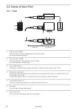
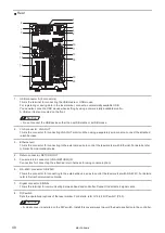
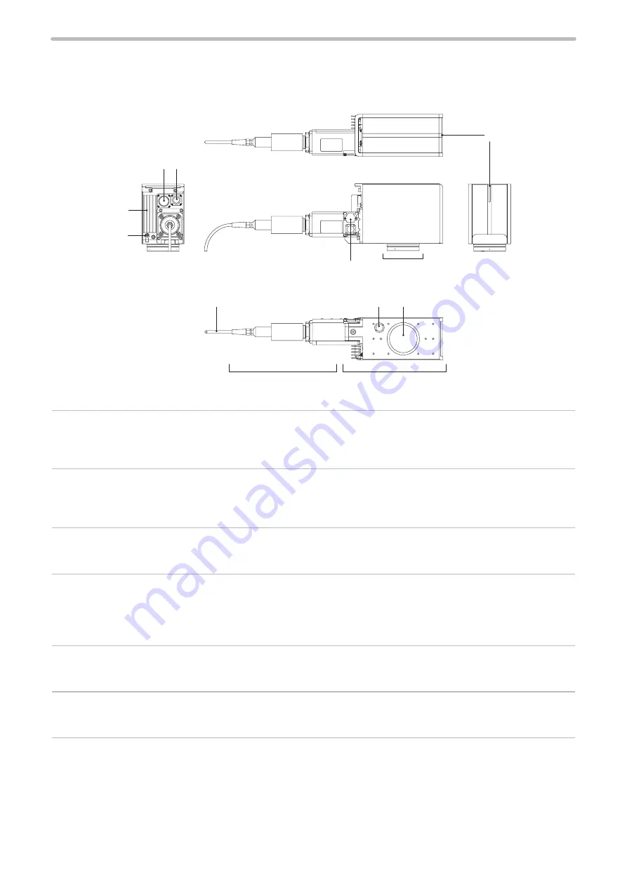
2-2-1 Head
4
7
1 2
10
3
6
8
9
5
Fiber unit
Scanner unit
1. Signal connector: SIGNAL
This is the terminal for communicating between head and controller.
Connect the attached signal cable.
2. Power connector: POWER
This is the connector for supplying the power to the head.
Connect the attached unit power cable.
3. Laser radiation indicator
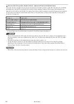
This indicator indicates the laser radiation state. Refer to “Safety functions on laser marker” (P.20).
4. Laser pointer emission port
The emission port of the red laser pointer radiated when using the dual pointer function. For details, refer to “2-3-6
Lasing position check” (P.58).
To use the dual pointer function, do not seal the laser pointer emission port at the installation.
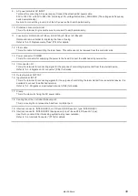
5. Frame ground terminal: F.G.
This is the terminal for ground. Be sure to connect it to earth permanently.
6. Fiber cable
This is the cable for transmitting the laser.
7. Laser emission port
The emission port of the marking laser and the guide laser.
ME-LPS-SSM-8
Summary of Contents for LP-S Series
Page 15: ...15 MEMO ME LPS SSM 8 ...
Page 26: ...26 Chapter 1 Specification ME LPS SSM 8 ...
Page 41: ...41 Chapter 2 Preparation ME LPS SSM 8 ...
Page 78: ...Chapter 3 Connection for External Control ME LPS SSM 8 ...
Page 126: ...Chapter 4 Maintenance ME LPS SSM 8 ...
Page 148: ...Troubleshooting ME LPS SSM 8 ...
Page 169: ...Index ME LPS SSM 8 ...
Page 172: ...172 MEMO No 9000 0066 16V ME LPS SSM 8 ...
Page 173: ...No 9000 0066 16V ...

