62
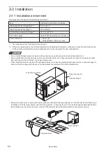
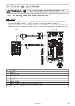
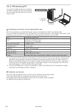
2-4-2 Connecting ground and power supply
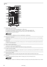
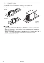
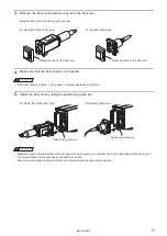
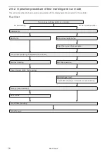
This section describes how to connect ground and power supply. For the AC power cable, use the attached AC power
cable. The power terminal, protective conductor terminal and frame ground terminal are located on the back side of the unit
as shown below.
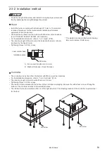
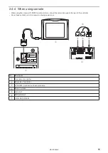
Power terminal
Controller
Head
Protective conductor
terminal
Frame ground
terminal: F.G.
WARNING
• Perform the connection of the Power Terminal Block with power-off state.
There is a risk of electrical shock.
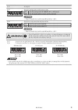
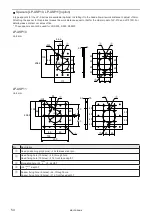
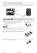
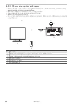
1.
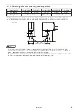
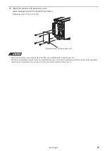
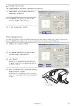
Connect the protective conductor terminal and the frame
ground terminal to the grounding part.
Screw size: M4
Tightening torque: 1.0N·m
ワㄐㄕㄊㄆ
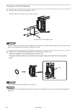
• Before connecting the power supply, connect the protective conductor terminal and the frame ground terminal
permanently to the grounding part.
• Install such that the controller housing and the head housing are at the same electric potential.
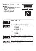
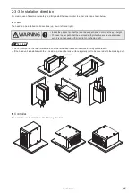
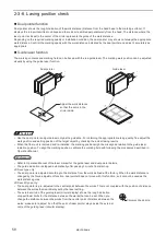
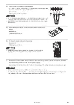
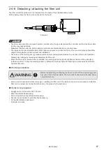
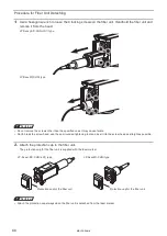
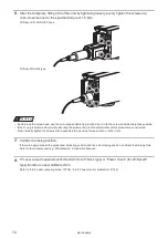
2.
Loosen two M3 screws of the power terminal casing and remove
it.
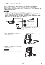
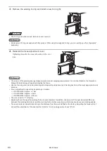
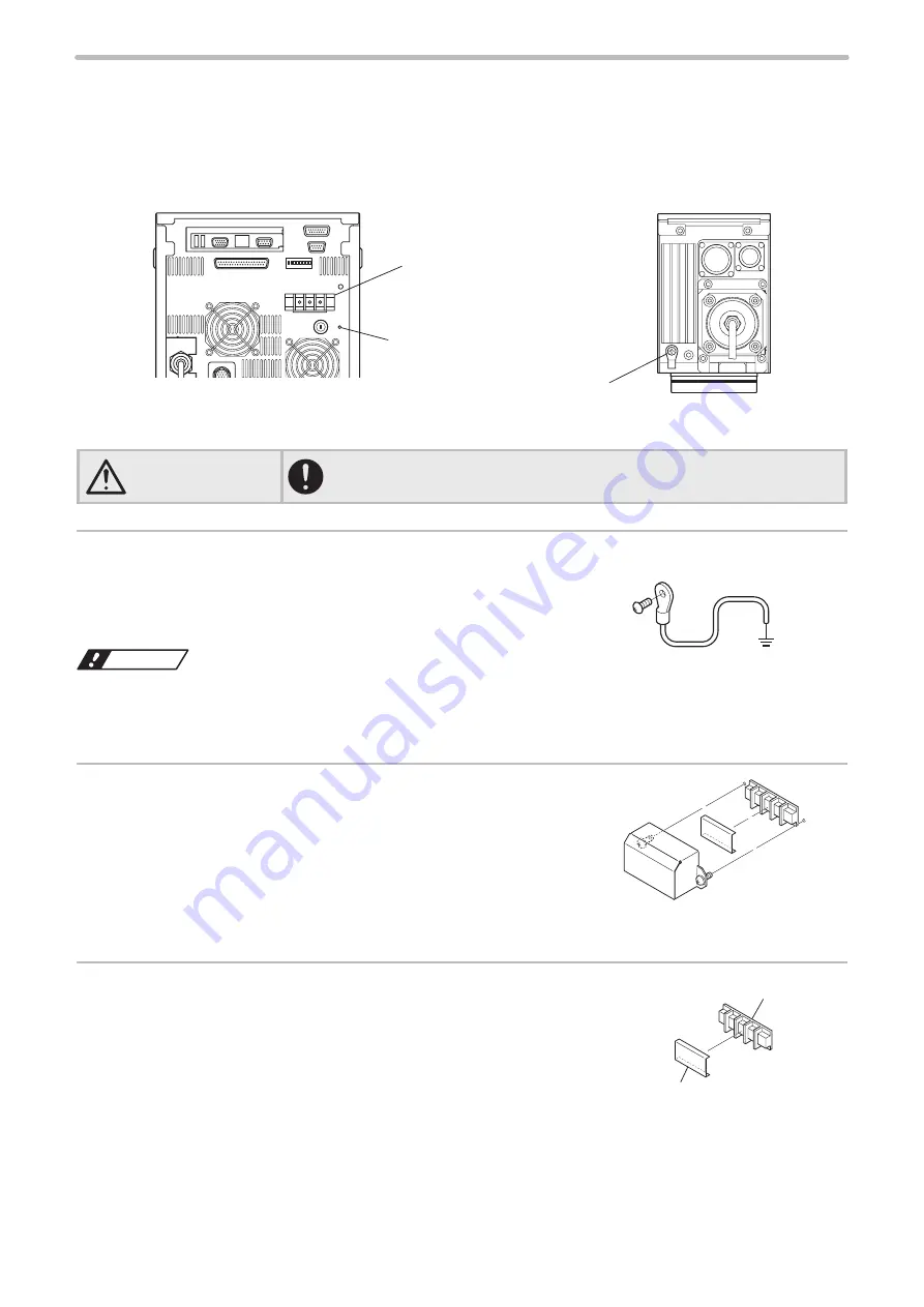
3.
Remove the resin cover on the terminal.
Protective conductor terminal /
Frame ground terminal
Ground
Terminal
Resin cover
ME-LPS-SSM-8
Summary of Contents for LP-S Series
Page 15: ...15 MEMO ME LPS SSM 8 ...
Page 26: ...26 Chapter 1 Specification ME LPS SSM 8 ...
Page 41: ...41 Chapter 2 Preparation ME LPS SSM 8 ...
Page 78: ...Chapter 3 Connection for External Control ME LPS SSM 8 ...
Page 126: ...Chapter 4 Maintenance ME LPS SSM 8 ...
Page 148: ...Troubleshooting ME LPS SSM 8 ...
Page 169: ...Index ME LPS SSM 8 ...
Page 172: ...172 MEMO No 9000 0066 16V ME LPS SSM 8 ...
Page 173: ...No 9000 0066 16V ...


