
64
2-4-3 When using PC
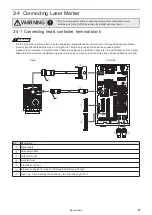
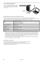
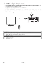
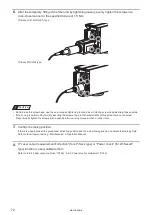
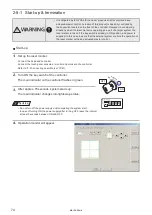
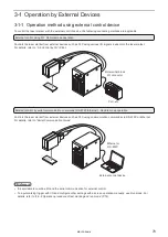
To use the PC installed the software in attached
CD-ROM “Laser Marker Utility” with online status,
connect the attached USB cable to the front side
of the controller.
Operating environment of Laser Marker NAVI plus
The PC setting software “Laser Marker NAVI plus” is stored in the attached CD-ROM “Laser Marker Utility”.
To use this software, install the data in the CD-ROM to the commercially available PC in the following environment. For the
installation procedures, refer to “Laser Marker NAVI plus Operation Manual” stored in the CD-ROM.
Item
Installation requirements
OS *1
Windows
®
10 Pro 32bit, 64bit
Windows
®
8.1 Pro 32bit, 64bit
Free area on hard disk
100MB or more
CD-ROM drive *2
1 set or more
USB port
USB1.1 and upper grade
Memory capacity
1GB or more
Display resolution
1024 x 768 pixels or above
Others
Pointing device such as a mouse and character input device such as a keyboard
*1 : OS versions of which Microsoft has ended support are excluded. The CPU type, memory capacity, hard-disk space,
and display function required to operate each OS should be provided in accordance with the recommendation of
Microsoft. Laser Marker NAVI plus can be installed in English, Simplified Chinese, German, Korean or Japanese. It
is preferred that the OS language corresponds to the installation language. If the OS language is other than these
supported languages, install Laser Marker NAVI plus in English.
*2 : To install the software on a PC without a CD-ROM drive, copy all CD-ROM data to the PC using external storage
media such as a USB flash drive before installation.
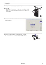
Installation procedures
Set the CD-ROM “Laser Marker Utility” to the PC and the installation will start automatically.
Install “Laser Marker Utility” by following the instructions shown on the screen.
If the installation screen does not appears, double-click on following file to start installation.
[CD-ROM]\Setup\LaserMarkerUtility\setup.exe
Front side of
controller
To USB connector B
PC
USB cable
ME-LPS-SSM-8
Summary of Contents for LP-S Series
Page 15: ...15 MEMO ME LPS SSM 8 ...
Page 26: ...26 Chapter 1 Specification ME LPS SSM 8 ...
Page 41: ...41 Chapter 2 Preparation ME LPS SSM 8 ...
Page 78: ...Chapter 3 Connection for External Control ME LPS SSM 8 ...
Page 126: ...Chapter 4 Maintenance ME LPS SSM 8 ...
Page 148: ...Troubleshooting ME LPS SSM 8 ...
Page 169: ...Index ME LPS SSM 8 ...
Page 172: ...172 MEMO No 9000 0066 16V ME LPS SSM 8 ...
Page 173: ...No 9000 0066 16V ...


