
90
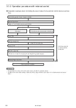
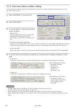
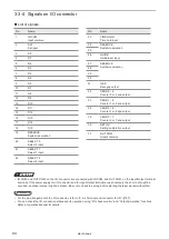
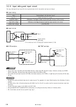
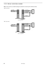
Input signal operation in I/O terminal
ンㄆㄇㄆㄓㄆㄏㄆ
• The ON/OFF listed in this section refers to the ON/OFF operations. It does not refer to the voltage level (High/Low).
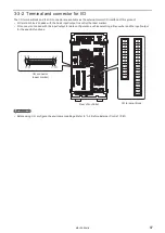
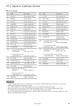
Terminal No.
Name / Description
X1
24V OUT: Internal power (power for input/output) + 24V DC (max. output current 300mA)
Power to operate the laser marker independently.
X1 and Y3 are the common terminal connected internally.
ワㄐㄕㄊㄆ
• Make sure to use X3 or Y1 for the 0V of the internal power 24V (X1 and Y3). Do not mix the connecting pattern for
using external and internal power supply.
• Do not connect anything to this when using the external power supply.
• When using the internal power supply (X1, X3, Y1, Y3), the total current of the power supply for the external device
and the consumption current for the I/O control should be less than 300mA.
X2
IN COM.: Input common
The common terminal for each input of the I/O terminal and I/O connector. IN COM. (X2) and IN COM.
(No.1) of I/O connector are the common terminal connected internally. In case of NPN connection, this
terminal is connected to the “+ (plus)” side of power which is used for control. In case of PNP connection,
this terminal is connected to the “- (minus)” side of power which is used for control.
ワㄐㄕㄊㄆ
• Do not invert the power wiring of I/O terminal and I/O connector. It may cause a failure. When this terminal is
connected to the power supply, it is not necessary to supply the power to the other IN COM. on I/O connector.
X3
0V OUT: Internal power (power supply for input/output) 0V
Power to operate the laser marker independently.
Y1 and X3 are the common terminal connected internally.
ワㄐㄕㄊㄆ
• Make sure to use X1 or Y3 for the internal power 0V (X3 and Y1). Do not mix the connecting pattern for using external
and internal power supply.
• Do not connect anything to this when using the external power supply.
X4
RESERVE: System reservation
Do not connect externally.
X5
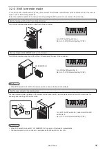
REMOTE IN: Remote mode input
While this input is turned on, the laser marker operates in the remote mode which can be controlled
externally by I/O and serial communication commands. To transit to the remote mode using this terminal,
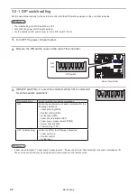
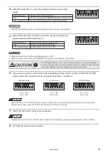
turn ON the DIP switch No. 5 in advance. Refer to “3-2-3 Shift to remote mode” (P.85).
X6
TRIG. IN: Trigger input
The signal to start marking (laser radiation). Starts marking by edge of input ON. This signal can be
accepted while the ready output (Y6) is turned ON.
When the equidistant marking to the flying object is set, marking operation is executed at regular
intervals while TRIG. IN is ON.
X7
X8
ENC.A: Encoder A phase input
ENC.B: Encoder B phase input
Encoder input at marking to movable bodies. Input up to 100kHz is possible for A and B phases
respectively. Use the [ENC.A] for input and connect the [ENC.B] to Input common if either of these
encoders are used.
ンㄆㄇㄆㄓㄆㄏㄆ
• X7 [ENC. A] and X8 [ENC. B] are not used with the LP-SxxxW type. Do not connect externally.
X9
LASER IN: Laser pumping input
Laser is being pumped (enable radiation) while the terminal remains in ON position. It takes about 20
seconds from starting the laser pumping input to completion of pumping.
This terminal is available when the DIP switch No. 2 is turned OFF.
ME-LPS-SSM-8
Summary of Contents for LP-S Series
Page 15: ...15 MEMO ME LPS SSM 8 ...
Page 26: ...26 Chapter 1 Specification ME LPS SSM 8 ...
Page 41: ...41 Chapter 2 Preparation ME LPS SSM 8 ...
Page 78: ...Chapter 3 Connection for External Control ME LPS SSM 8 ...
Page 126: ...Chapter 4 Maintenance ME LPS SSM 8 ...
Page 148: ...Troubleshooting ME LPS SSM 8 ...
Page 169: ...Index ME LPS SSM 8 ...
Page 172: ...172 MEMO No 9000 0066 16V ME LPS SSM 8 ...
Page 173: ...No 9000 0066 16V ...


