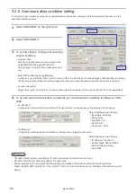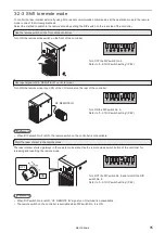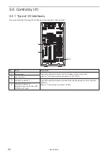
94
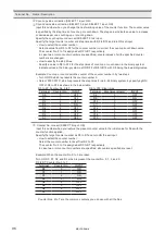
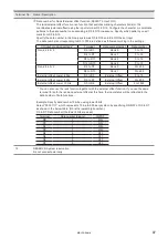
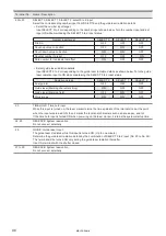
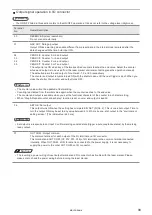
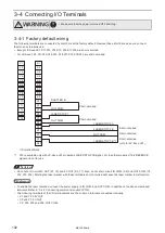
3-3-4 Signals on I/O connector
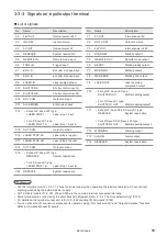
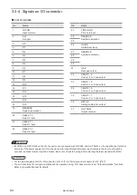
List of signals
No.
Name
1
IN COM.
Input common
2
SET
Set input
3
D0
4
D1
5
D2
6
D3
7
D4
8
D5
9
D6
10
D7
11
D8
12
D9
13
D10
14
D11
15
D12
16
D13
17
D14
18
D15
19
RESERVE
System reservation
20
SELECT 0
Select 0 input
21
SELECT 1
Select 1 input
22
SELECT 2
Select 2 input
No.
Name
23
TIME HOLD
Time hold input
24
RESERVE
System reservation
25
26
GUIDE
Guide laser input
27
RESERVE
System reservation
28
29
30
31
GAP
Date gap output
32
CEND 0 / 4
Counter 0 or 4 end output
33
CEND 1 / 5
Counter 1 or 5 end output
34
CEND 2 / 6
Counter 1 or 5 end output
35
CEND 3 / 7
Counter 3 or 7 end output
36
SET OK
Setting completion output
37
OUT COM.
Output common
ワㄐㄕㄊㄆ
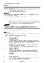
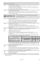
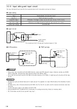
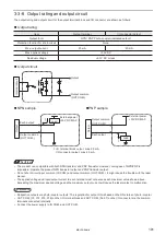
• IN COM. and OUT COM. on the I/O connector are connected with IN COM. and OUT COM. on the Input/Output terminal
internally. If the power supply for I/O connector and for Input/Output terminal are set inversely, the short out might be
occurred, and laser marker might be broken. Be sure to check the wiring before starting the laser marker without fail.
ンㄆㄇㄆㄓㄆㄏㄆ
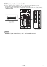
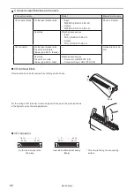
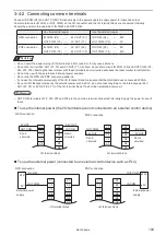
• For the pin arrangement of the I/O connector, refer to “3-3-2 Terminal and connector for I/O” (P.87).
• You can check the I/O connection status and its operation using “I/O check monitor” and “Output simulation” functions.
Refer to Operation Manual for details.
ME-LPS-SSM-8
Summary of Contents for LP-S Series
Page 15: ...15 MEMO ME LPS SSM 8 ...
Page 26: ...26 Chapter 1 Specification ME LPS SSM 8 ...
Page 41: ...41 Chapter 2 Preparation ME LPS SSM 8 ...
Page 78: ...Chapter 3 Connection for External Control ME LPS SSM 8 ...
Page 126: ...Chapter 4 Maintenance ME LPS SSM 8 ...
Page 148: ...Troubleshooting ME LPS SSM 8 ...
Page 169: ...Index ME LPS SSM 8 ...
Page 172: ...172 MEMO No 9000 0066 16V ME LPS SSM 8 ...
Page 173: ...No 9000 0066 16V ...

