99
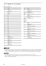
Output signal operation in I/O connector
ンㄆㄇㄆㄓㄆㄏㄆ
• The ON/OFF listed in this section refers to the ON/OFF operations. It does not refer to the voltage level (High/Low).
Terminal
No.
Name/Description
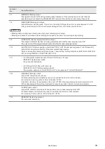
30
RESERVE: System reservation
Do not connect externally.
31
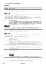
GAP OUT: Date gap output
Output ON as a warning when date different from preset date in the internal clock is marked after the
date changes with the time hold input ON.
32
33
34
35
CEND 0/4: Counter 0 or 4 end output
CEND 1/5: Counter 1 or 5 end output
CEND 2/6: Counter 2 or 6 end output
CEND 3/7: Counter 3 or 7 end output
The output turns ON when any of the two specified counters reaches the end value. Select the counter
whose end output is to be used from the laser marker environment setting (see the operation manual).
The default value is the end output of counters 0, 1, 2 and 3 respectively.
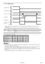
The counter end output remains turned ON with the shutter open until the next trigger is input. When you
close the shutter, the counter end output turns OFF.
ンㄆㄇㄆㄓㄆㄏㄆ
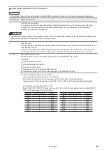
• The counter value will not be updated at test marking.
• Counting is activated from the initial value again when the counter reaches to the end value.
• The counter end output is available when you set the functional character of the counter in a character string.
• When “Step & Repeat counter at each step” function is set, counter end output is invalid.
36
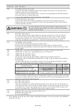
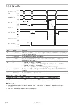
SET OK: Set output
This output turns ON when the setting has completed for SET IN (No. 2). This is one-shot output. Time to
turn the output ON may be set to any value between 2 to 510 ms by one-shot output in the “environment
setting screen”. (The initial value is 40 ms.)
ンㄆㄇㄆㄓㄆㄏㄆ
• Set output is a response to set input. Confirm marking enabled state (trigger input acceptance status) by the marking
ready output.
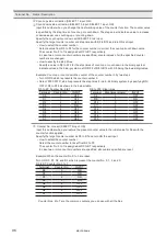
37
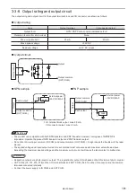
OUT COM.: Output common
The common terminal for each output of the I/O terminal and I/O connector.
This terminal and OUT COM. (Y2, X12, X15, X18) of I/O terminal are the common terminal connected
internally. When OUT COM. of I/O terminal is connected to the power supply, it is not necessary to
supply the power to the other OUT COM. on I/O connector.
ワㄐㄕㄊㄆ
• The inverting a power wiring of input/output terminal and I/O connector has trouble with the laser marker. Please
make sure to check the power wiring before running the laser marker.
ME-LPS-SSM-8
Summary of Contents for LP-S Series
Page 15: ...15 MEMO ME LPS SSM 8 ...
Page 26: ...26 Chapter 1 Specification ME LPS SSM 8 ...
Page 41: ...41 Chapter 2 Preparation ME LPS SSM 8 ...
Page 78: ...Chapter 3 Connection for External Control ME LPS SSM 8 ...
Page 126: ...Chapter 4 Maintenance ME LPS SSM 8 ...
Page 148: ...Troubleshooting ME LPS SSM 8 ...
Page 169: ...Index ME LPS SSM 8 ...
Page 172: ...172 MEMO No 9000 0066 16V ME LPS SSM 8 ...
Page 173: ...No 9000 0066 16V ...

