106
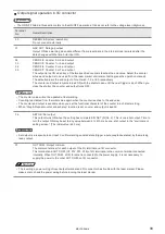
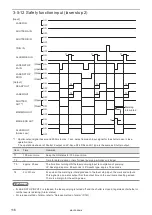
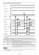
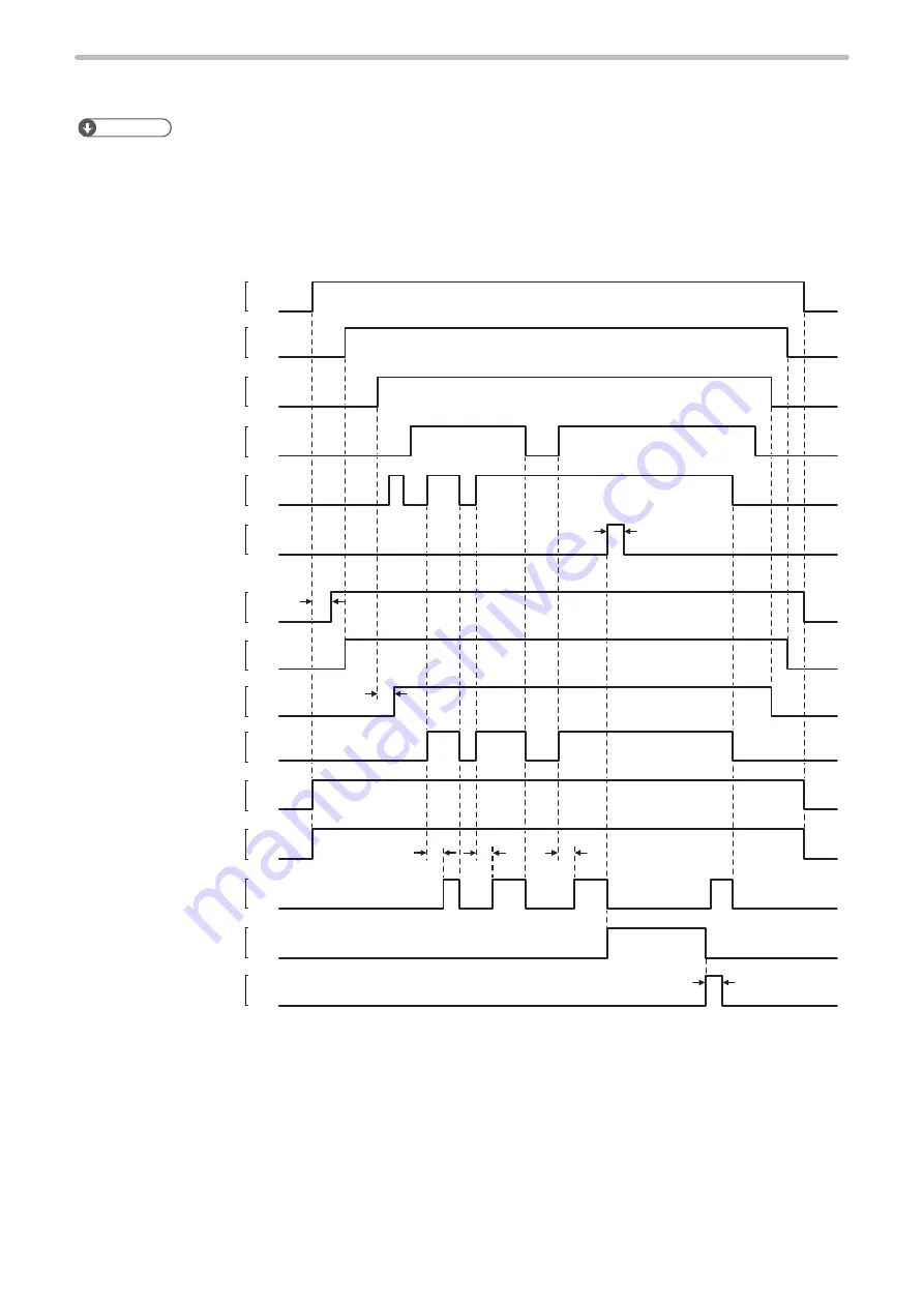
3-5 Timing Chart
ンㄆㄇㄆㄓㄆㄏㄆ
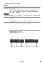
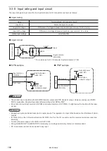
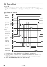
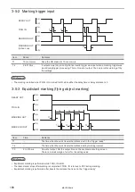
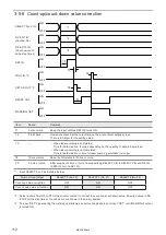
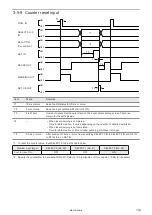
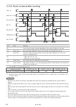
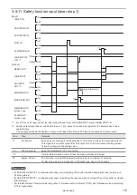
• ON/OFF on the timing chart does not intend to High/Low of voltage level. It intends to ON/OFF of operation.
• In the following timing charts, the timing of output operation corresponding to the each input has a small delay of 0 ms or
more.
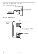
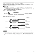
3-5-1 Basic input/output
ON
OFF
ON
OFF
ON
OFF
ON
OFF
ON
OFF
ON
OFF
ON
OFF
ON
OFF
ON
OFF
ON
OFF
ON
OFF
ON
OFF
ON
OFF
ON
OFF
ON
OFF
T1
T4
T5
T2
T3
T3
T3
*1
*3
[Input]
[Output]
Key switch
STANDBY OUT
READY OUT
MARKING OUT
MARK END OUT
REMOTE OUT
LASER OUT
LASER IN
TRIG. IN
SHUTTER
OUT *2
(Open)
(Open)
(Open)
(Close)
(Close)
(Close)
REMOTE IN
ALARM OUT
(Active Low)
WARNING OUT
(Active Low)
SHUTTER B
IN
SHUTTER A
IN
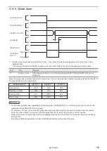
*1 : Shutter control input A is accepted and the shutter opens only when shutter control input B ON.
*2 : Shutter output signal has around 200ms to max. 1 sec. delay from each input signal for the shutter open / close
operation time.
The operation behavior of Shutter 2 output on LP-Sxxx-SF/LP-Sxxx-LS1 type is the same as Shutter output.
*3 : Turn OFF the key switch with the laser pumping OFF or shutter closed state.
ME-LPS-SSM-8
Summary of Contents for LP-S Series
Page 15: ...15 MEMO ME LPS SSM 8 ...
Page 26: ...26 Chapter 1 Specification ME LPS SSM 8 ...
Page 41: ...41 Chapter 2 Preparation ME LPS SSM 8 ...
Page 78: ...Chapter 3 Connection for External Control ME LPS SSM 8 ...
Page 126: ...Chapter 4 Maintenance ME LPS SSM 8 ...
Page 148: ...Troubleshooting ME LPS SSM 8 ...
Page 169: ...Index ME LPS SSM 8 ...
Page 172: ...172 MEMO No 9000 0066 16V ME LPS SSM 8 ...
Page 173: ...No 9000 0066 16V ...


