background image

26

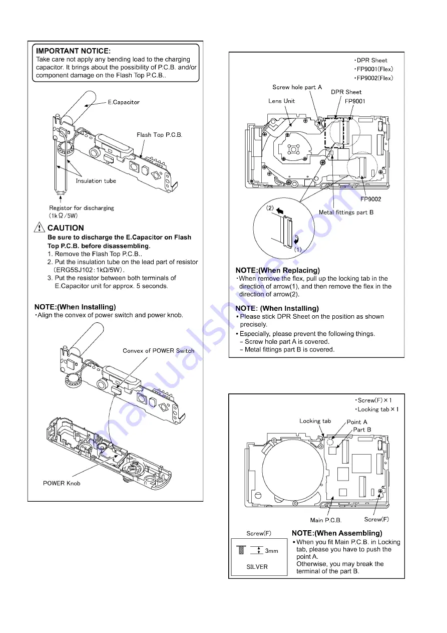
(Fig. D8)

8.3.6.

Removal of the Lens Unit

(Fig. D9)

8.3.7.

Removal of the Main P.C.B.

(Fig. D10)

Summary of Contents for Lumix DMC-FS35EB

Page 1: ...n is a violation of law ORDER NO DSC1102004CE B26 Digital Camera Model No DMC FS35EB DMC FS35EE DMC FS35EF DMC FS35EG DMC FS35EP DMC FH25P DMC FH25PC DMC FH25PR DMC FH25PU DMC FH25GA DMC FH25GC DMC FH...

Page 2: ...l Description About Lead Free Solder PbF 8 3 3 Important Notice 1 Other than U S A and Canadian Market 8 3 4 How to Define the Model Suffix NTSC or PAL model 9 4 Specifications 13 5 Location of Contro...

Page 3: ...g exposed to shock hazards 1 2 Leakage Current Cold Check 1 Unplug the AC cord and connect a jumper between the two prongs on the plug 2 Measure the resistance value with an ohmmeter between the jumpe...

Page 4: ...ing Procedure 1 Refer to the disassemble procedure and remove the necessary parts unit 2 Install the insulation tube onto the lead part of resistor ERG5SJ102 1k 5W An equivalent type of resistor may b...

Page 5: ...ces 4 Use only an antistatic solder removal device Some solder removal devices not classified as antistatic ESD protected can generate electrical charge sufficient to damage ES devices 5 Do not use fr...

Page 6: ...must not be used until a replacement cover is obtained A replacement fuse cover can be purchased from your local Panasonic Dealer If the fitted moulded plug is unsuitable for the socket outlet in you...

Page 7: ...t Type No ML421 Manufactured by Energy Company Panasonic Corporation It must never be subjected to excessive heat or discharge It must therefore only be fitted in requirement designed specifically for...

Page 8: ...it should be well molten and mixed with the original lead free solder Remove the remaining lead free solder on the P C B cleanly for soldering of the new IC Since the melting point of the lead free so...

Page 9: ...PR PU GA GC GF GH What is the difference is that the INITIAL SETTINGS data which is stored in Flash ROM mounted on MAIN P C B 3 4 1 Defining methods To define the model suffix to be serviced refer to...

Page 10: ...3 Turn the Power off If the unit is other than NORMAL PICTURE mode it does not display the initial settings menu Step 1 The temporary cancellation of INITIAL SETTINGS Set the REC PLAYBACK selector swi...

Page 11: ...ng MAIN P C B Step 5 Choose the model suffix in INITIAL SETTINGS Refer to CAUTION 1 Caution After replacing MAIN P C B The model suffix can been chosen JUST ONE TIME Once one of the model suffix have...

Page 12: ...ASE SET THE CLOCK in concernd language when the unit is turned on again When the unit is connected to PC with USB cable it is detected as removable media When the GT or GK model suffix is selected the...

Page 13: ...13 4 Specifications...

Page 14: ...timer Flash setting 11 Strap eyelet Be sure to attach the strap when using the camera to ensure that you will not drop it 12 Lens barrel 13 AV OUT DIGITAL socket 12 13 11 14 Camera ON OFF switch 15 Zo...

Page 15: ...are recorded using settings automatically selected by the camera Normal Picture Mode The subjects are recorded using your own settings My Scene Mode Pictures are taken using previously registered rec...

Page 16: ...code can be displayed by ordering the following procedure Preparation 1 Attach the Battery or AC Adaptor with a DC coupler to the unit NOTE Since this unit has built in memory it can be performed wit...

Page 17: ...17 3 Error Code List The error code consists of 8 bits data and it shows the following information...

Page 18: ...ack the concerned picture on the LCD display This function is achieved by utilizing maker note data stored in Exif data area of recorded picture file To proceed failure diagnosis use this ICS function...

Page 19: ...How to read 4 How to exit Simply turn the power off Since ICS function is executed under the condition of temporary cancellation of INITIAL SETTINGS it wake up with normal condition when turn off the...

Page 20: ...20 7 Service Fixture Tools 7 1 Service Fixture and Tools The following Service Fixture and tools are used for checking and servicing this unit...

Page 21: ...cing FLASH TOP P C B 1 Be sure to discharge the E capacitor on FLASH TOP P C B Refer to HOW TO DISCHARGE THE E CAPACITOR ON FLASH TOP P C B The E capacitor voltage is not lowered soon even if the AC C...

Page 22: ...22 8 Disassembly and Assembly Instructions 8 1 Disassembly Flow Chart This is a disassembling chart When assembling perform this chart conversely 8 2 PCB Location...

Page 23: ...op Case Unit Fig D6 3 Screws D Frame Plate Tripod Fixing Plate PS8001 Connector Top Case Unit 5 Flash Top P C B Fig D7 2 Locking tabs AF Panel Light 2 Screws E 3 Locking tabs Flash Top P C B 2 Locking...

Page 24: ...24 Fig D2 8 3 2 Removal of the Sub P C B Fig D3 8 3 3 Removal of the LCD Unit Fig D4...

Page 25: ...25 Fig D5 8 3 4 Removal of the Top Case Unit Fig D6 8 3 5 Removal of the Flash Top P C B Fig D7...

Page 26: ...26 Fig D8 8 3 6 Removal of the Lens Unit Fig D9 8 3 7 Removal of the Main P C B Fig D10...

Page 27: ...ack Door Fig D12 NOTE When Installing Make sure to confirm the following points when installing The Screw is tightened enough Installing conditions are fine No distortion no abnormal space No dust and...

Page 28: ...e 5 Apply grease RFKZ0472 as shown on THE APPLICA TION OF GREASE METHOD in the figure 6 Apply a light coat of grease using an object similar to a toothpick 7 The drive frame unit and penetration cam f...

Page 29: ...29 9 Remove the 4 solders C 10 Remove the lens FPC unit to the direction of arrow 3 8 4 2 Removal of the Master Flange Unit 1 Unscrew the 4 screws C 2 Remove the master flange unit...

Page 30: ...2nd lens frame unit both sides cam frame 2nd 3rd direct frame 3rd lens frame unit from the fixed frame unit drive frame unit penetration cam frame 1st direct frame unit 8 4 4 Removal of the 2nd Lens...

Page 31: ...irection of the arrow 8 4 6 Removal of the 3rd Lens Frame Unit 1 Remove the 3rd lens frame unit in the direction of the arrow 8 4 7 Removal of the 2nd Lens Frame Unit 1 Turn the 2nd lens frame unit in...

Page 32: ...frame unit in the direction of the arrow 8 4 9 Removal of the Drive Penetration Frame Unit 1 Remove the drive penetration frame unit in the direction of the arrow 8 5 Assembly Procedure for the Lens 8...

Page 33: ...33 8 5 2 Phase alignment of the Drive Pene tration Frame Unit and Fixed Frame Unit 8 5 3 Phase alignment of the 2nd Lens Frame Unit and Both Sides Cam Frame...

Page 34: ...4 Phase alignment of the 3rd Lens Frame Unit and 2nd Lens Frame Unit Both Sides Cam Frame 8 5 5 Phase alignment of the 2nd 3rd Direct Frame and 2nd Lens Frame Unit Both Sides Cam Frame 3rd Lens Frame...

Page 35: ...35 8 5 6 Phase alignment of the 2nd Lens Frame Unit Both Sides Cam Frame 2nd 3rd Direct Frame 3rd Lens Frame Unit and 1st Lens Frame Unit...

Page 36: ...Frame 2nd 3rd Direct Frame 3rd Lens Frame Unit and 1st Direct Frame Unit 8 5 8 Phase alignment of the 1st Direct Frame Unit 1st Lens Frame Unit 2nd Lens Frame Unit Both Sides Cam Frame 2nd 3rd Direct...

Page 37: ...37 8 5 9 Install of the Master Flange Unit 8 5 10 Install of the Lens FPC Unit and Zoom Motor...

Page 38: ...Application of Grease Method The grease application parts of lens unit are as follows Apply grease additionally in the specified position if necessary When the grease is applied use a toothpick and a...

Page 39: ...gain done after completing the alignment Otherwise the camera may not work properly Therefore as a warning the camera display a warning symbol on the LCD monitor every time the camera is turned off Re...

Page 40: ...camera to Temporary cancellation of the initial settings 3 Select the SETUP menu From the SETUP menu select ROM BACKUP NOTE This item is not listed on the customer s SETUP menu 4 When this ROM_BACKUP...

Page 41: ...itor displays SERVICE MODE Refer to Fig 3 1 9 3 1 2 Status Adjustment Flag Setting Reset Not yet adjusted the status flag condition 1 After pressing the DISP button the LCD monitor dis plays the Flag...

Page 42: ...identally start the adjustment again 3 Do not press any buttons keys until the default menu Fig 3 5 is displayed on the LCD monitor Otherwise adjustment data may not be stored properly 4 If the adjust...

Page 43: ...table shows the relation between the replaced part and the Necessary Adjustment When a part is replaced make sure to perform the necessary adjustment s in the order indicated The table below shows al...

Page 44: ...44...

Page 45: ...ompleting the alignment Otherwise the camera will not work properly Therefore as a warning the camera display a warning symbol on the LCD monitor every time the camera is turned off 2 Confirm that sta...

Page 46: ...CD Panel with your hand When cleaning the lens use air Blower to blow off the dust When cleaning the LCD Panel dampen the lens cleaning paper with lens cleaner and the gently wipe the its surface Note...

Page 47: ...K Black Type K Black Type A Blue Type only P PC PU GK GN V Violet Type only P PC PR PU GT R Red Type except PR GT Name of Signal OFTR FEP This signal is connected to the FEP schematic diagram Circuit...

Page 48: ...tronic circuit tester high impedance with the chassis taken as standard Therefore there may exist some errors in the voltage values depending on the internal impedance of the DC circuit tester REF No...

Page 49: ...I F USB I F MAIN MICROPROCESSOR FLASH TOP OPERATION UNIT IC1001 POWER SHUTTER IC9101 SYSTEM IC IC6002 ZOOM OIS CONTROL LENS DRIVE LCD DRIVE AV OUT DIGITAL TERMINAL 28mm 224mm IC7101 GYRO SENSOR AMP I...

Page 50: ...P2 VDD2 AVDD CN3 AGND CP4 VCOML CP5 VCC 1 8 VGH CP7 VCS CP5 VCOM CP3 LED SDA SCEN SCEN SDA HSYNC NA DIN7 DIN5 DIN3 DIN1 NA DCLK VDD 1 8 VSYNC VDD VCC VSS GND CN1 GND CN2 CP1 CP3 AGND VCL VCOMH CN4 PCD...

Page 51: ...uF 315V RL8001 RL8002 D8002 B0ECFR000003 LB8001 J0JCC0000415 3 4 1 2 8 7 5 6 B1JBLP000030 Q8001 1 3 2 4 S8004 K0F111A00541 L0CBAY000093 M8001 C LAMP LAMP S S TRG_G TRG FIRST TRG SECOND SLEEVE_GND SAFE...

Page 52: ...H3 H3 HL HL MSUB MSUB V16 V16 V16 V12Z V12Z V13X V13X V13Y V13Y V13Z V13Z V14 V14 V15 V15 V15D V15D V12X V12X V12 V12 V11 V11 V10 V10 V8 V8 V7 V7 V6 V6 V5 V5 V9 V9 V12Y V12Y V1A V1A V2B V2B V2A V2A V...

Page 53: ...FLEX SCHEMATIC DIAGRAM TO MAIN MAIN CN CIRCUIT FP9002 A2 A1 C4 C3 B1 B2 STEPPING MOTOR FOCUS MOTOR UNIT G 40 41 A3 G1 G2 G3 G4 COIL COIL DC MOTOR ZOOM MOTOR UNIT D PHOTO SENSOR ZOOM ENCODER 1 F PHOTO...

Page 54: ...003 F8001 10 6 5 1 IC8100 2 1 8 7 6 5 4 3 2 1 Q8001 R8002 R8003 R8005 R8006 R8013 R8021 R8032 TL8004 VA8001 C8006 CL8011 CL8032 CL8031 Component Side 1 4 N M L K J I H G DMC FS35 FH25 FH24 Flash Top P...

Page 55: ...S 9 CL8004 CL8006 ET8005 F8021 3 2 1 L8001 15 10 5 1 30 25 20 16 PS8001 TL8001 TL8002 TL8007 4 3 2 1 P8002 Component Side 2 4 DMC FS35 FH25 FH24 Flash Top P C B...

Page 56: ...C8017 C8018 C8019 1 2 3 4 5 6 7 S8002 4 3 2 1 S 8 0 0 3 4 3 2 1 S 8 0 0 4 C8022 LB8001 6 5 4 3 2 1 S8001 C8014 Foil Side 11 10 9 8 7 6 5 4 3 2 1 H G F E D C B A 3 4 Foil Side DMC FS35 FH25 FH24 Flash...

Page 57: ...S 11 CL8001 C8009 C8015 C8016 1 1 ET8004 RL8001 RL8002 R8037 R8038 1 2 4 5 S8002 TL8003 4 3 2 1 T8001 1 2 M8001 DMC FS35 FH25 FH24 Flash Top P C B Foil Side 4 4 21 20 19 18 17 16 15 14 13 12 11...

Page 58: ...32 30 25 22 21 20 15 12 1110 5 1 IC3101 6 5 4 3 2 1 Q3101 C3101 R3101 R3108 R3107 R3102 TH3101 FT3101 DMC FS35 FH25 FH24 CCD Flex P C B 10 9 8 7 6 5 4 3 2 1 G F E D C B A Foil Side Component Side S5...

Page 59: ...ZOOM MOTOR UNIT D1 D D2 Pin 41 Pin 1 FOCUS MOTOR UNIT G2 G G3 G1 G4 A1 A3 A2 CO BARREL ENCODER FULL RETRACT A OIS UNIT B B9 B8 B7 B6 B5 B4 C4 C3 SHUTTER UNIT C C1 C2 B1 B2 B3 B10 B11 B12 E F2 ZOOM EN...

Page 60: ...S 14...

Page 61: ...r this item After the discontinuation of this assembly in production it will no longer be available 5 Supply of CD ROM in accordance with license protection is allowable as replacement parts only for...

Page 62: ...Z04000057 CONNECTOR 4P 1 PS8001 K1KB30AA0123 CONNECTOR 30P 1 Q8001 B1JBLP000030 TRANSISTOR 1 E S D R8002 ERJ3GEYJ104V M RESISTOR CH 1 10W 100K 1 R8003 ERJ3GEYJ121V M RESISTOR CH 1 10W 120 1 R8005 ERJ6...

Page 63: ...CASE UNIT 1 K B3 VHD2082 SCREW 1 K R A V 9 VYK4N37 REAR CASE UNIT 1 R B4 VHD2194 SCREW 1 S 9 VYK4N38 REAR CASE UNIT 1 A B4 VHD2195 SCREW 1 K R A V 9 VYK4N39 REAR CASE UNIT 1 V B5 VHD2194 SCREW 1 S 9 1...

Page 64: ...NISH PORTUGUESE 214 VPK4672 PACKING CASE 1 25P S 214 VPK4677 PACKING CASE 1 25P K 214 VPK4682 PACKING CASE 1 25P R 214 VPK4687 PACKING CASE 1 25P A 214 VPK4692 PACKING CASE 1 25P V 214 VPK4673 PACKING...

Page 65: ...ASE 1 25GK K 311 VFF0794 S CD ROM 1 25GC 314 VPK4699 PACKING CASE 1 25GK R SOFT INSTRUCTION BOOK SPC See Notes 314 VPK4700 PACKING CASE 1 25GK A 312 VQC8057 O I SOFTWARE 1 35EG 314 VPK4690 PACKING CAS...

Page 66: ...12 9 9 1 9 2 B2 B7 B8 B3 B9 26 B10 31 1 31 B17 B18 B19 7 5 3 33 32 B16 1 4 25 30 23 24 22 29 10 8 8 1 B11 B12 B13 B6 B1 B4 B5 B106 B107 B105 B108 B109 B110 B111 B101 102 B102 B103 B104 104 3 104 2 10...

Page 67: ...S 21 S7 2 Packing Parts and Accessories Section 1 211 208 212 213 200 215 201 202 220 PC only 221 PC only 206 204 205 214 Stick the UPC LABEL Ref No 221 for PC model on the original UPC place...

Page 68: ...cking Parts and Accessories Section 2 314 311 308 312 313 300 315 325 GT only DMC FS35EE EF EG EP DMC FH25GA GF DMC FS35EB DMC FH25GC GH DMC FH25GN DMC FH25GK GT 322 320 321 319 DMC FH25PR 323 302 301...

Reviews: