background image

© Panasonic Corporation 2008. Unauthorized copy-
ing and distribution is a violation of law.

ORDER NO. DSC0810042CE

B26

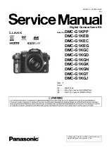
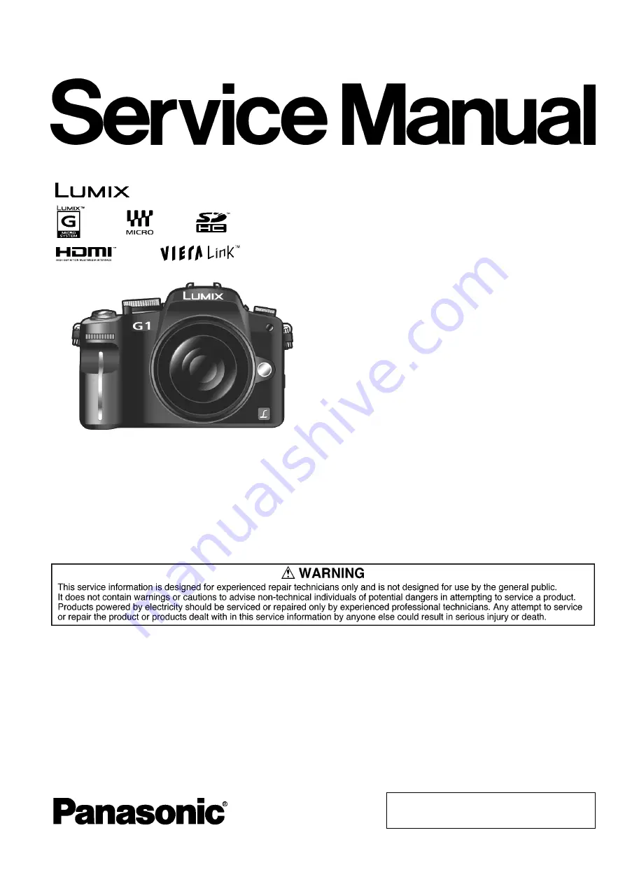
Digital Camera/Lens Kit

Model No.

DMC-G1KPP

       DMC-G1KEB
       DMC-G1KEC
       DMC-G1KEG
       DMC-G1KGC
       DMC-G1KGD
       DMC-G1KGH
       DMC-G1KGK
       DMC-G1KGN
       DMC-G1KGT
       DMC-G1KGJ

Vol. 1

Colour
(K)...........Black Type
(A)...........Blue Type (except GD/GN/GT/GJ)
(R)...........Red Type (except GD/GN/GT/GJ)

Summary of Contents for Lumix DMC-G1KEB

Page 1: ... violation of law ORDER NO DSC0810042CE B26 Digital Camera Lens Kit Model No DMC G1KPP DMC G1KEB DMC G1KEC DMC G1KEG DMC G1KGC DMC G1KGD DMC G1KGH DMC G1KGK DMC G1KGN DMC G1KGT DMC G1KGJ Vol 1 Colour K Black Type A Blue Type except GD GN GT GJ R Red Type except GD GN GT GJ ...

Page 2: ...roduction 8 3 2 Important Notice 8 3 3 General Description About Lead Free Solder PbF 9 3 4 How to Define the Model Suffix NTSC or PAL model 10 4 Specifications 13 5 Location of Controls and Components 14 6 Service Mode 34 6 1 Error Code Memory Function 34 7 Troubleshooting Guide 36 8 Service Fixture Tools 39 8 1 Service Fixture and Tools 39 8 2 Clean Box 40 8 3 Service Position 41 9 Disassembly a...

Page 3: ...exposed to shock hazards 1 2 Leakage Current Cold Check 1 Unplug the AC cord and connect a jumper between the two prongs on the plug 2 Measure the resistance value with an ohmmeter between the jumpered AC plug and each exposed metal lic cabinet part on the equipment such as screwheads connectors control shafts etc When the exposed metal lic part has a return path to the chassis the reading should ...

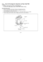
Page 4: ...rging Procedure 1 Refer to the disassemble procedure and Remove the necessary parts unit 2 Put the insulation tube onto the lead part of Resistor ERG5SJ102 1kΩ 5W An equivalent type of resistor may be used 3 Put the resistor between both terminals of capacitor on FLASH SUB PCB for approx 5 seconds 4 After discharging confirm that the capacitor voltage is lower than 10V using a voltmeter Fig F1 ...

Page 5: ...ices 4 Use only an antistatic solder removal device Some solder removal devices not classified as antistatic ESD protected can generate electrical charge sufficient to damage ES devices 5 Do not use freon propelled chemicals These can generate electrical charges sufficient to damage ES devices 6 Do not remove a replacement ES device from its protective package until immediately before you are read...

Page 6: ...g must not be used until a replacement cover is obtained A replacement fuse cover can be purchased from your local Panasonic Dealer If the fitted moulded plug is unsuitable for the socket outlet in your home then the fuse should be removed and the plug cut off and disposed of safety There is a danger of severe electrical shock if the cut off plug is inserted into any 13 ampere socket If a new plug...

Page 7: ...ever be subjected to excessive heat or discharge It must therefore only be fitted in requirement designed specifically for its use Replacement batteries must be of same type and manufacture They must be fitted in the same manner and location as the original battery with the correct polarity contacts observed Do not attempt to re charge the old battery or re use it for any other purpose It should b...

Page 8: ...he Support Information from NWBG VDBG AVC web site in TSN system 2 The full adjustment procedures must be performed after replacing the MOUNT BOX BLOCK otherwise picture quality can not be meet with specification 3 2 1 2 About Main PCB Ref 1 1 This Service Manual does not contain the repair service information for MAIN P C B Ref 1 because it requires special facil ities and equipment a Schematic d...

Page 9: ...han that of the normal solder Distinction of PCB Lead Free Solder being used Service caution for repair work using Lead Free Solder PbF The lead free solder has to be used when repairing the equipment for which the lead free solder is used Definition The letter of PbF is printed on the PCB using the lead free solder To put lead free solder it should be well molten and mixed with the original lead ...

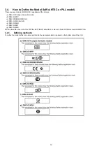
Page 10: ...tic model b DMC G1KPP c DMC G1KEB EC EG GH d DMC G1KGC GJ GN e DMC G1KGD f DMC G1KGT g DMC G1KGK What is the difference is that the INITIAL SETTINGS data which is stored in Flash ROM mounted on MAIN PCB 3 4 1 Defining methods To define the model suffix to be serviced refer to the nameplate which is putted on the bottom side of the Unit ...

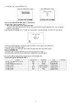
Page 11: ...Drive mode lever to SINGLE While keep pressing DISPLAY and FILM MODE buttons simultaneously turn the Power on Step 2 The cancellation of initial setting Press the PLAYBACK button then playback the picture Press FILM MODE and UP of Cursor buttons simultaneously then turn the Power off Step 3 Turn the Power on Set the mode dial to P and then turn the Power on Step 4 Display the INITIAL SETTING While...

Page 12: ...rm the display of PLEASE SET THE CLOCK in English when the unit is turned on again Step 6 CONFIRMATION The display shows PLEASE SET THE CLOCK when turn the Power on again When the unit is connected to PC with USB cable it is detected as removable media 1 As for your reference Default setting condition is given in the following table Default setting After INITIAL SETTINGS MODEL VIDEO OUTPUT LANGUAG...

Page 13: ...13 4 Specifications ...

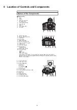
Page 14: ...SPLAY button 18 Delete button Preview button 19 MENU SET button 20 Cursor buttons ISO AF mode Function button Assign Menu to button It is convenient to register Menu that is used often ASPECT RATIO QUALITY METERING MODE I EXPOSURE GUIDE LINE WB White balance 2 3 7 6 5 4 1 8 11 13 16 17 9 10 12 14 15 20 18 19 21 Focus mode dial 22 Flash open lever 23 Drive mode lever Single Burst Auto bracket Self ...

Page 15: ...ripod receptacle When you use a tripod make sure the tripod is stable when the camera is attached to it Lens H FS014045 LUMIX G VARIO 14 45 mm F3 5 5 6 ASPH MEGA O I S 40 Tele 41 Lens surface 42 Focus ring 43 Wide 44 Zoom ring 45 O I S switch 46 Contact point 47 Lens fitting mark Battery charger AC adaptor 48 Power input socket AC IN 49 CHARGE indicator 50 Power output socket DC OUT 51 Battery hol...

Page 16: ... The shutter speed is automatically determined by the Shutter priority AE mode The aperture value is automatically determined by the Manual exposure mode The exposure is adjusted by the aperture value and the shutter speed which are manually adjusted Custom mode Use this mode to take pictures with previously registered settings My color mode Easily check the color of light brightness and vividness...

Page 17: ... on the aperture value of the lens you are using s Take some test pictures with the lens you are using s Lens with the Four Thirds mount specification can be used by using the mount adaptor DMW MA1 optional However AFC mode and continuous AF function cannot be used Only manual focus is possible when using a lens that is not compatible with the Contrast AF There are some restrictions to some other ...

Page 18: ...ting the pictures s Recorded data may be damaged or pictures may be distorted by strong magnetic fields created by speakers or large motors s Electromagnetic wave radiation generated by microprocessors may adversely affect the camera disturbing the pictures s If the camera is adversely affected by electromagnetic equipment and stops functioning properly turn the camera off and remove the battery o...

Page 19: ... a commercially available blower brush Be careful not to blow too strongly s Do not put the blower brush further inside than the lens mount s Do not let the blower brush touch the image sensor as the image sensor may get scratched s Do not use any objects except a blower brush to clean the image sensor s If you cannot remove the dirt or dust with the blower consult the dealer or your nearest Servi...

Page 20: ...d s Inserting a damaged battery in the camera will damage the camera Bring charged spare batteries when going out s Be aware that the operating time of the battery becomes shorter in low temperature conditions such as at a ski resort s When you travel do not forget to bring the battery charger supplied so that you can charge the battery in the country that you are travelling in Dispose of unusable...

Page 21: ...amera and store it again after it has completely discharged s We recommend storing the camera with a desiccant silica gel when you keep it in a closet or a cabinet s Check all the parts before taking pictures when you have not used the camera for a long period of time s Recorded data may be damaged or lost if the camera breaks down due to inappropriate handling Panasonic will not be liable for any...

Page 22: ...ich can be set at one time when MULTI has been selected for DELETE MULTI or FAVORITE has been exceeded Reduce the number of pictures set and then repeat the operation s More than 999 favourites have been set CANNOT BE SET ON THIS PICTURE s DPOF PRINT cannot be set for pictures not based on the DCF standard MEMORY CARD ERROR FORMAT THIS CARD s This card has a format which is not recognised by the c...

Page 23: ... DISPLAYED FOR 4 3 TV PICTURE IS DISPLAYED FOR 16 9 TV s The video cable is connected to the camera Press MENU SET if you want to delete this message at once Select TV ASPECT in the SETUP menu if you want to change the TV aspect s This message also appears when the USB connection cable is connected to the camera only In this case connect the other end of the USB connection cable to a PC or a print...

Page 24: ... the burst mode is set s When taking a picture of auto bracket HIGHLIGHT s Multi playback s Calendar playback s Playback zoom POWER SAVE s When using the AC adaptor s When connecting to a PC or a printer s During a slide show AUTO LCD OFF s When using the AC adaptor s When connecting to a PC or a printer AUTO POWER LCD s When playing back pictures Direction detection function s When non compatible...

Page 25: ... and in mode s mode s and in mode s in mode s mode s Å and in SCENE MODE s mode White balance bracket s and in mode s mode s and in mode s in mode s mode s Å and in SCENE MODE s mode s When multi film bracket is set s When set to or SENSITIVITY s Advanced scene mode s mode Intelligent ISO sensitivity s mode s mode s Advanced scene mode s mode FILM MODE s mode Multi film bracket s Advanced scene mo...

Page 26: ...CT AF AREA s Advanced scene mode s mode s mode AF ASSIST LAMP s mode s and in mode s Å in SCENE MODE FAVORITE s Pictures taken with ROTATE s Protected pictures ROTATE DISP s Multi playback s Calendar playback DPOF PRINT s Pictures taken with RESIZE s Pictures taken with or TRIMMING s Pictures taken with or ASPECT CONV s Pictures taken with or s Pictures taken with 9 or 8 ...

Page 27: ... ECONOMY mode etc s If you connect to a TV compatible with VIERA Link with a HDMI mini cable optional and turn off the power on the TV with the remote control for the TV the power on this unit also turns off If you are not using VIERA Link set VIERA Link to OFF s Is the temperature of the battery excessively high or low If it is it will take longer than usual to charge the battery or charging may ...

Page 28: ...e balance bracket s The subject is beyond the focus range of the camera s There is camera shake jitter or the subject is moving slightly s Is FOCUS PRIORITY in the CUSTOM MENU menu set to OFF In this case the picture may not be properly focused even if AFS or AFC in focus mode is set s Is the AF lock applied in inappropriate way s The shutter speed will become slower and the optical image stabiliz...

Page 29: ...on the lens used picture may be warped slightly or see colours in the edge depending on the zoom factor due to the characteristics of the lens Also the peripherals of the image might look warped because the perspective is enhanced when the wide angle is used This is not a malfunction s Is the flash closed Slide the OPEN lever to open the flash s The flash is activated 2 times The interval between ...

Page 30: ...ar to maintain the brightness of the LCD monitor This does not affect the pictures you are recording s The LCD monitor may flicker for a few seconds after turning the camera on indoors under fluorescent light This is not a malfunction s This is characteristic of MOS sensors which serve as the camera s pickup sensors This is not a malfunction This does not affect the pictures you are recording s Th...

Page 31: ...e check well before formatting s Is the clock in the camera set properly s Images edited on a PC or images recorded on other cameras might display a different date to the recorded date during the Calendar Playback s Is it a picture that has been recorded with other equipment In such cases these pictures may be displayed with a deteriorated picture quality Playback The picture being played back is ...

Page 32: ...it back to On Refer to the operating instructions of the TV for details s Is the camera connected to the PC correctly s Is the camera recognised by the PC correctly Set to PC in USB MODE Disconnect the USB connection cable Connect it again while the card is inserted in the camera s Pictures cannot be printed using a printer which does not support PictBridge Set to PictBridge PTP in USB MODE When u...

Page 33: ...f you do not use the camera for a long time the clock may be reset When the message PLEASE SET THE CLOCK appears set the clock again When you take a picture before setting the clock 0 00 0 0 0 is recorded s When you perform an operation after taking a certain action the pictures may be recorded in folders with different numbers from the ones used prior to the operation s If the battery was inserte...

Page 34: ...aneously turn the Power on 2 The display of error code Press FILM MODE MENU SET and LEFT of Cursor buttons simultaneously with the step 1 condition The display is changed as shown below when the above buttons is pressed simultaneously Normal display Error code display Operation history display Normal display Example of Error Code Display 3 The change of display The error code can be memorized 16 e...

Page 35: ...ation error HARD VENUS A D Flash 28 0 0000 Flash charging capacitor did not been fully charged within 20 seconds FLASH ROM Data Area 2B 0 0001 Flash ROM data reading error is detected when the unit turns ON 0002 Flash ROM data writing error is detected when the unit turns OFF Program Area 0005 Firmware update error SYSTEM IC Initialization 2C 0 0001 Clock IC initialization failure error SOFT CPU R...

Page 36: ...36 7 Troubleshooting Guide ...

Page 37: ...37 ...

Page 38: ...38 ...

Page 39: ...39 8 Service Fixture Tools 8 1 Service Fixture and Tools The following Service Fixture and tools are used for checking and servicing this unit ...

Page 40: ... recommended 8 2 2 Introduction of Clean box One of our recommended clean box is as shown below less than class 10 000 Federal Standard 209D It consists of Air clean unit and Clean hood As for the Air clean unit refer to the Jig Information on the Support Information from NWBG VDBG AVC web site in TSN sys tem ...

Page 41: ...d 2 Be careful of the high voltage circuit on FLASH SUB PCB 3 DO NOT allow other parts to touch the high voltage circuit on FLASH SUB PCB No Parts No Connection Form 1 VFK1441 FP9001 MAIN FP7701 AF ASSIST FP7351 REMOTE FP7300 LP SW 8PIN 0 5 FFC 2 RFKZ0477 FP9006 MAIN LVF UNIT 45PIN 0 3 FFC 3 VFK1950 FP9005 MAIN FP7201 LCD IF 33PIN 0 3 FFC 4 VFK1576DC202 P9003 MAIN CL4901 CL4902 HINGE SW 2PIN CONNE...

Page 42: ...42 9 Disassembly and Assembly Instructions 9 1 Disassembly Flow Chart 9 2 PCB Location ...

Page 43: ... Screws O 1 Screw P Battery Case Unit 7 Flash P C B Fig D9 2 Screws Q P8506 Connector Buzzer Solder 4 points P8502 Connector Flash P C B 8 Flash Sub P C B Unit Fig D10 Kapton Tape Flash PI Tape 1 Screw R 1 Locking tab Battery Lock Spring Flash Sub P C B Unit 9 AF Assist P C B Remote P C B LP SW P C B Fig D11 FP7701 Flex 1 Screw S AF Light Case AF Assist P C B Fig D12 2 Screws T 3 Screws U Remote H...

Page 44: ...44 9 3 1 Removal of the Rear Case Unit Fig D1 Fig D2 ...

Page 45: ...45 9 3 2 Removal of the Top Case Unit Fig D3 9 3 3 Removal of the LVF Unit Fig D4 ...

Page 46: ...46 9 3 4 Removal of the Main P C B Fig D5 9 3 5 Removal of the Front Case Unit Fig D6 ...

Page 47: ...47 Fig D7 9 3 6 Removal of the Battery Case Unit Fig D8 9 3 7 Removal of the Flash P C B Fig D9 ...

Page 48: ...48 9 3 8 Removal of the Flash Sub P C B Unit Fig D10 9 3 9 Removal of the AF Assist P C B Remote P C B and LP SW P C B Fig D11 ...

Page 49: ...49 Fig D12 9 3 10 Removal of the Optical Sensor Unit Fig D13 9 3 11 Removal of the LCD Unit Fig D14 ...

Page 50: ...50 Fig D15 9 3 12 Removal of the LCD TFT Unit Fig D16 ...

Page 51: ...and dust to get into the inside part component of the unit 3 Do not touch the surface of the lens glasses with your fingers 4 Blow off the dust on the surface of the lens with a blower brush 5 Use lens cleaning KIT BK VFK1900BK Interchangeable Lens H FS014045 NOTE 1 When installing the screws be sure to use the torque driver RFKZ0456 and tighten the screws with specified torque men tioned on the a...

Page 52: ...52 ...

Page 53: ...53 9 4 1 Removal of the Decoration Ring NOTE Be careful not touch the lens surface with Tweezers when removing the Decoration Ring 9 4 2 Phase alignment of the Decoration Ring ...

Page 54: ...the MAIN PCB proceed the EEPROM data backup from the unit After replacing the MAIN PCB overwrite the EEPROM data with backup data from the unit before proceeding the adjustment inspection NOTE 3 After replacing the MOUNT BOX BLOCK the mount box data has to be stored to the unit before proceeding the adjustment inspection For more details consult the adjustment instruction which is available togeth...

Page 55: ...55 11 Maintenance ...

Page 56: ...56 ...

Page 57: ... DMC G1KGC DMC G1KGD DMC G1KGH DMC G1KGK DMC G1KGN DMC G1KGT DMC G1KGJ Digital Camera Name of Signal OFTR FEP This signal is connected to the FEP schematic diagram Circuit name being connected 6 Use the parts number indicated on the Replacement Parts List 7 Indication on Schematic diagrams 5 The voltage being indicated here may be include observational error deviation due to internal resistance an...

Page 58: ...n the voltage values depending on the internal impedance of the DC circuit tester REF No PIN No POWER ON Q8501 1 0 Q8501 2 0 Q8501 3 0 Q8501 4 0 Q8501 5 3 3 Q8501 6 3 3 Q8501 7 3 3 Q8501 8 3 3 Q8502 1 10 1 Q8502 2 10 1 Q8502 3 0 Q8502 4 0 Q8502 5 10 1 Q8502 6 10 1 QR8501 1 0 QR8501 2 5 6 QR8501 3 0 QR8501 4 6 2 QR8501 5 5 6 QR8501 6 0 QR8502 E 0 QR8502 C 5 6 QR8502 B 0 QR8503 E 0 QR8503 C 0 QR8503...

Page 59: ...CROPROCESSOR FLASH TOP OPERATION UNIT IC1001 POWER IC9101 SYSTEM IC IC6007 OIS CONTROL LENS DRIVE LCD DRIVE DIGITAL V OUT TERMINAL COLOR LCD PANEL LENS UNIT REMOTE TERMINAL BUZZER 3 0 PANEL X6001 24MHz X9101 32 768kHz IC5001 HDMI HDMI TERMINAL DMC G1 OVERALL BLOCK DIAGRAM IC6005 BUS SWITCH HOT SHOE IC9003 IC9004 IC9005 LENS CONTACT TERMINAL SSWF SHUTTER UNIT IC9801 Q9801 T9801 QR9005 QR9006 IC6004...

Page 60: ...CCD1 10 CCD2 0 CCD2 2 CCD2 4 CCD2 6 CCD2 8 CCD2 10 GND AFE VD AFE CS2 AFE SCK MAICO 5V MAICO 3R5V MAICO 2R2V GND MAICO PW SW2 STRB TRG LSLDP GND ASSIST LED A ASSIST LED A ASSIST LED K ASSIST LED K 4 3 2 1 FP7701 AF ASSIST P C B FOIL SIDE BACK BAT BACK BAT REMOTE GND 4 3 2 1 FP7351 REMOTE P C B COMPONENT SIDE D GND D GND LPSW LPSW 4 3 2 1 FP7300 LP SW P C B FOIL SIDE FRONT FPC HOT SHOE HOT SHOE FPC...

Page 61: ...6 704 704 704 704 56 A29 A176 06A56 A10A 6 5 61A 66 4 A 6 4 250 62 6 657 14 56A A81 6 5 5 5 6 50 19 56 A64 4 8 5 0 6 50 DMC G1K Flash Schematic Diagram 10 9 8 7 6 5 4 3 2 1 G F E D C B A CAUTION FOR CONTINUED PROTECTION AGAINST FIRE HAZARD REPLACE ONLY WITH THE SAME TYPE 3 0A 32V FUSE ATTENTION POUR UNE PROTECTION CONTINUE LES RISQUES D INCENDIE N UTILISERQUE DES FUSIBLE DE MÉME TYPE 3 0A 32V 3 0A...

Page 62: ...hematic Diagram QPHKFGPVKCN 7PVKN 0 2 59 259 259 A 0 A 0 4 528 05 4 4 59 QPHKFGPVKCN 7PVKN 0 2 14 2 55 56A A 55 56A A 61 4106A 2 4 55 56A A 55 56A A DMC G1K LP SW Schematic Diagram DMC G1K AF Assist Schematic Diagram 10 9 8 7 6 5 4 3 2 1 G F E D C B A ...

Page 63: ...hematic Diagram QPHKFGPVKCN 7PVKN 2 0 2 0 2 A 2 8 5 8 8 8 1 85 0 5 0 0 0 0 0 0 5 5 5 0 0 0 8 8 1 8 2 2 2 2 2 2 2 2 2 0 0 0 0 0 0 0 8 8 0 0 0 0 0 0 0 0 A 075 0 0 A2 75 4 8 176 8 8 176 176 176 176 176 176 176 176 176 176 176 176 176 176 176 61 8 A5 A5 176 A 5 0 A4 5 6 0 56 A 61 6 4 4 DMC G1K Remote Schematic Diagram 10 9 8 7 6 5 4 3 2 1 G F E D C B A ...

Page 64: ...S4 8 Flash Sub Schematic Diagram DMC G1K Flash Sub Schematic Diagram QPHKFGPVKCN 7PVKN 4 4 47 704 A 0 56A A81 6 8 W QPHKFGPVKCN 7PVKN 59 4 4 4 A 0 A59 5285 25 4 A 0 A59 DMC G1K Hinge SW Schematic Diagram 10 9 8 7 6 5 4 3 2 1 G F E D C B A ...

Page 65: ...S 9 S5 Print Circuit Board 4 2 2 2 2 4 4 4 G 34 G 34 G 34 2 2 2 3 3 6 34 4 4 4 4 4 4 4 4 4 4 4 4 4 4 4 DMC G1K Flash P C B 10 9 8 7 6 5 4 3 2 1 G F E D C B A Foil Side Component Side S5 1 Flash P C B ...

Page 66: ...S 10 S5 2 AF Assist P C B S5 3 LP SW P C B 59 2 2 DMC G1K AF Assist P C B DMC G1K LP SW P C B Foil Side 10 9 8 7 6 5 4 3 2 1 G F E D C B A Foil Side Component Side ...

Page 67: ...S 11 S5 4 Remote P C B 4 2 DMC G1K Remote P C B 10 9 8 7 6 5 4 3 2 1 G F E D C B A Foil Side Component Side ...

Page 68: ...S 12 S5 5 LCD IF P C B DMC G1K LCD IF P C B Component Side 10 9 8 7 6 5 4 3 2 1 G F E D C B A Component Side S5 5 1 LCD IF P C B Component Side ...

Page 69: ...S 13 S5 5 2 LCD IF P C B Foil Side 2 2 2 DMC G1K LCD IF P C B Foil Side 10 9 8 7 6 5 4 3 2 1 G F E D C B A Foil Side ...

Page 70: ...S 14 S5 6 Hinge SW P C B S5 7 Flash Sub P C B 59 Foil Side 4 4 4 4 DMC G1K Flash Sub P C B DMC G1K Hinge SW P C B Component Side 10 9 8 7 6 5 4 3 2 1 G F E D C B A Foil Side Component Side ...

Page 71: ...Be sure to make your orders of replacement parts according to this list 2 IMPORTANT SAFETY NOTICE Components identified with the mark have the special characteristics for safety When replacing any of these components use only the same type 3 Unless otherwise specified All resistors are in OHMS K 1 000 OHMS All capacitors are in MICRO FARADS uf P uuF 4 The marking RTL indicates the retention time i...

Page 72: ...VCSG C7207 ECJ1VB1A105K C CAPACITOR CH 10V 1U 1 P8503 K1KA02B00292 CONNECTOR 2P 1 PAVCSG C7208 ECJ1VB1A105K C CAPACITOR CH 10V 1U 1 P8504 K1KA02BA0022 CONNECTOR 2P 1 PAVCSG C7209 ECJ1VB1C105K C CAPACITOR CH 16V 1U 1 P8506 K1KA02BA0022 CONNECTOR 2P 1 PAVCSG C7210 ECJ1VB1A105K C CAPACITOR CH 10V 1U 1 P8507 K1MN22BA0272 CONNECTOR 22P 1 PAVCSG C7211 ECJ1VB1A105K C CAPACITOR CH 10V 1U 1 Q8501 B1JBLP000...

Page 73: ...OM 1 R B21 VHD1754 SCREW 1 13 VYK2Y66 LCD TFT UNIT 1 B26 XQN16 BJ11FN SCREW 1 14 VEP59057A LCD IF P C B 1 RTL B27 XQN16 BJ11FN SCREW 1 15 VYK2Y63 LCD CASE UP UNIT 1 A B28 XQN16 BJ4FN SCREW 1 15 VYK2Y62 LCD CASE UP UNIT 1 K B29 XQN16 BJ4FN SCREW 1 15 VYK2Y64 LCD CASE UP UNIT 1 R B31 VHD2090 SCREW 1 17 VYK2Y65 LCD SHIELD CASE UNIT 1 B32 VHD2090 SCREW 1 18 VGQ0B55 LCD BL BEZEL SHEET 1 B33 VHD2090 SCR...

Page 74: ...R UNIT 1 R PAVCSG B122 VHD2062 A SCREW 1 PAVCSG 118 F2AZZ2310001 FLASH CHARGING CAPACITOR 1 C7100 PAVCSG B123 XQN16 B2FN SCREW 1 PAVCSG 119 K4ZZ04000050 BATTERY CATCHER 1 P8501 PAVCSG 120 K0RE00300017 FRONT DIAL UNIT 1 PAVCSG 121 VEP58067A AF ASSIST P C B 1 RTL E S D PAVCSG 122 VYK2Y58 FRONT CASE UNIT 1 A PAVCSG 122 VYK2Y56 FRONT CASE UNIT 1 K PAVCSG 122 VYK2Y60 FRONT CASE UNIT 1 R PAVCSG 123 VGK3...

Page 75: ...ME 2 UNIT 1 Not supplied 208 LENS MAIN BLOCK UNIT 1 Not supplied 209 VMG1855 FLOATING RUBBER 1 210 VMG1855 FLOATING RUBBER 1 211 VMG1855 FLOATING RUBBER 1 212 VMG1847 DUST PROOF RING 1 B201 XQN14 B3FN SCREW 1 B202 XQN14 B3FN SCREW 1 B203 XQN14 B3FN SCREW 1 B204 XQN14 BJ4FNK SCREW 1 B205 XQN14 BJ4FNK SCREW 1 B206 XQN14 BJ4FNK SCREW 1 B207 XQN14 BJ4FNK SCREW 1 B208 XQN2 AJ5FN SCREW 1 B209 XQN2 AJ5FN...

Page 76: ... GC GH 427 K2CR2CA00003 AC CORD W PLUG 1 GD 411 VPF1294 BAG POLYETHYLENE 1 GK EB GD GN GT GJ 428 K2CJ2DA00008 AC CORD W PLUG 1 GN 412 VQT1U52 O I SOFTWARE 1 PP 429 K2CA2CA00020 AC CORD W PLUG 1 GK ENGLISH CANADIAN FRENCH 429 JSX0102 AC CORD W PLUG 1 PP SPANISH PORTUGUESE 429 K2CA2CA00027 AC CORD W PLUG 1 GT 412 VQT1U54 O I SOFTWARE 1 EC 446 VKF4385 BODY CAP 1 SPANISH PORTUGUESE SWEDISH 447 VQL1V18...

Page 77: ...45 B50 B51 8 28 B105 156 130 B110 B111 B107 B47 131 126 5 B106 129 132 133 124 B112 121 B109 B108 B114 B113 B115 120 128 135 B37 B38 B31 B32 127 134 B35 B11 B6 B3 B4 147 145 148 142 32 B16 B17 B122 B117 B116 B118 B119 B120 B121 136 141 146 B20 B21 33 144 139 B5 4 3 143 B8 B9 9 B26 B27 137 138 19 14 18 13 17 23 22 15 B13 B12 B14 B15 B28 B29 B123 B18 B19 151 150 149 21 11 12 B39 B10 B36 B7 115 109 B...

Page 78: ...S7 2 Camera Lens Section S 22 208 204 205 207 B204 B205 B206 B207 209 210 211 203 212 202 206 B212 B213 B208 B209 B210 B211 B201 B202 B203 ...

Page 79: ...ts and Accessories Section S 23 403 402 404 405 423 406 400 446 422 421 425 424 449 414 418 417 412 416 408 448 409 411 407 447 DMC G1KEB GC GH DMC G1EC EG GC GJ DMC G1KGN 428 DMC G1KGD DMC G1KPP GK GT 429 420 426 427 ...

Reviews: