14
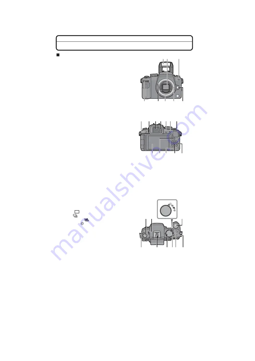
5 Location of Controls and Components
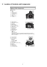
Names of the Components
Camera body
1
Flash
2
Sensor
3
Self-timer indicator
AF assist lamp
4
Lens release button
5
Lens lock pin
6
Mount
7
Lens fitting mark
8
Front dial
9
[LVF/LCD] button
10 Diopter adjustment dial
11
Viewfinder
12 Eye sensor
13 Playback button
14 [AF/AE LOCK] button
15 Camera ON/OFF switch
16 LCD monitor
17 [DISPLAY] button
18 Delete button/
Preview button
19 [MENU/SET] button
20 Cursor buttons
/ISO
/AF mode
/Function button
Assign Menu to
button. It is convenient to register Menu that is used often.
[ASPECT RATIO]/[QUALITY]/[METERING MODE]/[I.EXPOSURE]/[GUIDE LINE]
/WB (White balance)
2
3
7 6
5
4
1
8
11
13
16 17
9 10
12
14 15
20
18
19
21 Focus mode dial
22 Flash open lever
23 Drive mode lever
Single:
Burst:
Auto bracket:
Self-timer:
24 Shutter button
25 Focus distance reference mark
26 Hot shoe
27 Mode dial
28 Status indicator
29 [Q.MENU] button
30 [FILM MODE] button
25
26
22
21
23
24
30
29
28
27
Summary of Contents for Lumix DMC-G1KEB
Page 13: ...13 4 Specifications ...
Page 36: ...36 7 Troubleshooting Guide ...
Page 37: ...37 ...
Page 38: ...38 ...
Page 42: ...42 9 Disassembly and Assembly Instructions 9 1 Disassembly Flow Chart 9 2 PCB Location ...
Page 44: ...44 9 3 1 Removal of the Rear Case Unit Fig D1 Fig D2 ...
Page 45: ...45 9 3 2 Removal of the Top Case Unit Fig D3 9 3 3 Removal of the LVF Unit Fig D4 ...
Page 46: ...46 9 3 4 Removal of the Main P C B Fig D5 9 3 5 Removal of the Front Case Unit Fig D6 ...
Page 50: ...50 Fig D15 9 3 12 Removal of the LCD TFT Unit Fig D16 ...
Page 52: ...52 ...
Page 55: ...55 11 Maintenance ...
Page 56: ...56 ...

