17
About the Lens
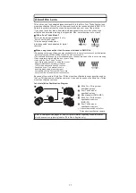
This unit can use the dedicated lenses compatible to the Micro Four Thirds System lens
mount specification (Micro Four Thirds mount) such as the lenses included in DMC-G1K.
Select a lens that matches the scene being recorded and your use of the pictures.
If you use a lens other than a dedicated interchangeable lens, auto focus cannot be
activated and accurate metering is not possible. Also, some functions will not work.
“Micro Four Thirds Mount”
This is the lens mount standard for the
“Micro Four Thirds System”.
This was newly developed as
interchangeable lens dedicated for digital
cameras.
When using lenses other than the lenses included in DMC-G1K
s
Depending on the type of lens, you may not be able to use some functions such as the direction
detection function, [STABILIZER], Quick AF and Continuous AF.
s
The available flash range etc. differs depending on the aperture value of the lens you are using.
s
Take some test pictures with the lens you are using.
s
Lens with the Four Thirds™ mount
specification can be used by using the mount
adaptor (DMW-MA1; optional). However,
[AFC] mode and continuous AF function
cannot be used. Only manual focus is
possible when using a lens that is not
compatible with the Contrast AF. There are
some restrictions to some other functions too.
Because of its structure, Micro Four Thirds mount specification lenses cannot be used on
the Four Thirds mount specification cameras. It can only be used on the Micro Four Thirds
mount specification cameras.
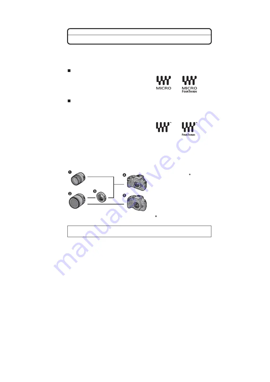
Lens Installation Combination Diagram
Micro Four Thirds mount
specification lens
Four Thirds mount
specification lens
Mount adaptor (DMW-MA1)
Micro Four Thirds mount
specification camera
(DMC-G1)
Four Thirds mount
specification camera
It cannot be mounted on the Four
Thirds mount specification camera.
Refer to catalogues/Web pages for most current information regarding compatible lenses.
http://panasonic.co.jp/pavc/global/cs (This Site is English only.)
Summary of Contents for Lumix DMC-G1KEB
Page 13: ...13 4 Specifications ...
Page 36: ...36 7 Troubleshooting Guide ...
Page 37: ...37 ...
Page 38: ...38 ...
Page 42: ...42 9 Disassembly and Assembly Instructions 9 1 Disassembly Flow Chart 9 2 PCB Location ...
Page 44: ...44 9 3 1 Removal of the Rear Case Unit Fig D1 Fig D2 ...
Page 45: ...45 9 3 2 Removal of the Top Case Unit Fig D3 9 3 3 Removal of the LVF Unit Fig D4 ...
Page 46: ...46 9 3 4 Removal of the Main P C B Fig D5 9 3 5 Removal of the Front Case Unit Fig D6 ...
Page 50: ...50 Fig D15 9 3 12 Removal of the LCD TFT Unit Fig D16 ...
Page 52: ...52 ...
Page 55: ...55 11 Maintenance ...
Page 56: ...56 ...

