22
Message Display
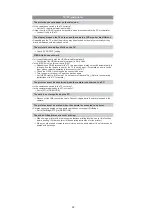
Confirmation messages or error messages will be displayed on the screen in some cases.
The major messages are described below as examples.
[THIS MEMORY CARD IS LOCKED]
The Write-Protect switch on the SD Memory Card and the SDHC Memory Card are
moved to [LOCK]. Move the switch back to unlock it.
[NO VALID PICTURE TO PLAY]
Record a picture or insert a card with a recorded picture and then play it.
[THIS PICTURE IS PROTECTED]
Delete the picture after cancelling the protect setting.
[THIS PICTURE CANNOT BE DELETED]/[SOME PICTURES CANNOT BE DELETED]
s
Pictures not based on the DCF standard cannot be deleted.
If you want to delete some pictures, format the card after saving necessary data on a PC
etc.
[NO ADDITIONAL SELECTIONS CAN BE MADE]
s
The number of pictures, which can be set at one time when [MULTI] has been selected for
[DELETE MULTI] or [FAVORITE] has been exceeded.
Reduce the number of pictures set, and then repeat the operation.
s
More than 999 favourites have been set.
[CANNOT BE SET ON THIS PICTURE]
s
[DPOF PRINT] cannot be set for pictures not based on the DCF standard.
[MEMORY CARD ERROR
FORMAT THIS CARD?]
s
This card has a format which is not recognised by the camera.
Format the card again with the camera after saving necessary data on a PC etc.
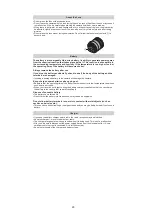
[PLEASE CHECK THAT THE LENS IS ATTACHED CORRECTLY]
s
Check that the lens is attached correctly and then turn the camera off and on.
If the message persists, contact the dealer or your nearest Service Centre.
[MEMORY CARD PARAMETER ERROR]
Use a card compatible with this unit.
s
You can only use an SDHC Memory Card if using cards with 4 GB or more capacity.
[MEMORY CARD ERROR
PLEASE CHECK THE CARD]
s
An error has occurred accessing the card.
Insert the card again.
s
Or try with a different card.
Summary of Contents for Lumix DMC-G1KEB
Page 13: ...13 4 Specifications ...
Page 36: ...36 7 Troubleshooting Guide ...
Page 37: ...37 ...
Page 38: ...38 ...
Page 42: ...42 9 Disassembly and Assembly Instructions 9 1 Disassembly Flow Chart 9 2 PCB Location ...
Page 44: ...44 9 3 1 Removal of the Rear Case Unit Fig D1 Fig D2 ...
Page 45: ...45 9 3 2 Removal of the Top Case Unit Fig D3 9 3 3 Removal of the LVF Unit Fig D4 ...
Page 46: ...46 9 3 4 Removal of the Main P C B Fig D5 9 3 5 Removal of the Front Case Unit Fig D6 ...
Page 50: ...50 Fig D15 9 3 12 Removal of the LCD TFT Unit Fig D16 ...
Page 52: ...52 ...
Page 55: ...55 11 Maintenance ...
Page 56: ...56 ...


