28
s
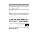
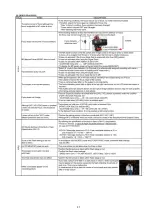
Is the mode dial correctly set?
s
Is the card inserted?
s
Is there any memory remaining on the card?
Delete the pictures which are not necessary to increase the available memory.
s
Is the subject focused?
At the time of purchase, the camera is set so that you cannot take a picture until the subject
is brought into focus. If you want to be able to take a picture when you press the shutter
button fully even if the subject is not focused, set [FOCUS PRIORITY] in the [CUSTOM
MENU] menu to [OFF].
s
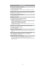
Picture might look whitish when lens or image sensor gets dirty with finger print or similar.
If the lens is dirty turn the camera off and then gently wipe the lens surface with a soft dry
cloth.
Refer to (Cleaning) when the image sensor gets dirty.
Check that the exposure is correctly compensated.
s
Is the AE lock applied in inappropriate way?
Unset the settings of white balance bracket.
s
The subject is beyond the focus range of the camera.
s
There is camera shake (jitter) or the subject is moving slightly.
s
Is [FOCUS PRIORITY] in the [CUSTOM MENU] menu set to [OFF]?
In this case, the picture may not be properly focused even if [AFS] or [AFC] in focus mode is
set.
s
Is the AF lock applied in inappropriate way?
s
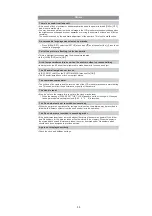
The shutter speed will become slower and the optical image stabilizer function may not work
properly when taking pictures especially in dark places.
We recommend holding the camera firmly with both hands when taking pictures.
We recommend using a tripod and the self-timer when taking pictures with a slow
shutter speed.
s
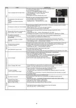
Is the number of recordable pictures 2 or less?
Recording
The picture cannot be recorded.
The shutter does not activate.
The recorded picture is whitish.
The recorded picture is too bright or dark.
2 or 3 pictures are taken at one time.
The subject is not focused properly.
The recorded picture is blurred.
The optical image stabilizer is not effective.
Taking pictures using white balance bracket is not possible.
Summary of Contents for Lumix DMC-G1KEB
Page 13: ...13 4 Specifications ...
Page 36: ...36 7 Troubleshooting Guide ...
Page 37: ...37 ...
Page 38: ...38 ...
Page 42: ...42 9 Disassembly and Assembly Instructions 9 1 Disassembly Flow Chart 9 2 PCB Location ...
Page 44: ...44 9 3 1 Removal of the Rear Case Unit Fig D1 Fig D2 ...
Page 45: ...45 9 3 2 Removal of the Top Case Unit Fig D3 9 3 3 Removal of the LVF Unit Fig D4 ...
Page 46: ...46 9 3 4 Removal of the Main P C B Fig D5 9 3 5 Removal of the Front Case Unit Fig D6 ...
Page 50: ...50 Fig D15 9 3 12 Removal of the LCD TFT Unit Fig D16 ...
Page 52: ...52 ...
Page 55: ...55 11 Maintenance ...
Page 56: ...56 ...

