32
s
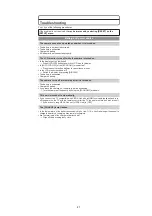
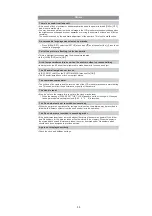
Is the camera connected to the TV correctly?
Set the TV input to external input mode.
s
Output from the [HDMI] socket is not possible when it is connected to the PC or the printer.
Connect it only to the TV.
s
Depending on the TV model, the pictures may be extended horizontally or vertically or they
may be displayed with their edges cut off.
Check [TV ASPECT] setting.
s
Is it connected properly with the HDMI mini cable (optional)?
Confirm that the HDMI mini-cable (optional) is firmly fitted.
s
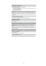
Is the [VIERA Link] on this unit set to [ON]?
Depending on HDMI terminal of the TV, the input channel may not switch automatically. In
this case, use the remote control for the TV to switch input. (For details on how to switch
input, please read the operating instructions for the TV.)
Check the VIERA Link setting on the connected device.
Turn the power to the unit off and then back on again.
Set [VIERA Link] to [Off] on the TV and then turn it back to [On]. (Refer to the operating
instructions of the TV for details.)
s
Is the camera connected to the PC correctly?
s
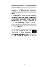
Is the camera recognised by the PC correctly?
Set to [PC] in [USB MODE].
Disconnect the USB connection cable. Connect it again while the card is inserted in the
camera.
s
Pictures cannot be printed using a printer which does not support PictBridge.
Set to [PictBridge(PTP)] in [USB MODE].
When using a printer with a trimming or borderless printing function, cancel this function
before printing. (For details, refer to the operating instructions for the printer.)
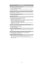
When you order photo studios to print pictures, ask the photo studio if the pictures can be
printed with both ends.
TV, PC and printer
The picture does not appear on the television.
The display areas on the TV screen and the camera’s LCD monitor are different.
The picture is not displayed fully on the TV.
VIERA Link does not work.
The picture cannot be transferred when the camera is connected to a PC.
The card is not recognised by the PC.
The picture cannot be printed when the camera is connected to a printer.
The ends of the pictures are cut at printing.
Summary of Contents for Lumix DMC-G1KEB
Page 13: ...13 4 Specifications ...
Page 36: ...36 7 Troubleshooting Guide ...
Page 37: ...37 ...
Page 38: ...38 ...
Page 42: ...42 9 Disassembly and Assembly Instructions 9 1 Disassembly Flow Chart 9 2 PCB Location ...
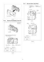
Page 44: ...44 9 3 1 Removal of the Rear Case Unit Fig D1 Fig D2 ...
Page 45: ...45 9 3 2 Removal of the Top Case Unit Fig D3 9 3 3 Removal of the LVF Unit Fig D4 ...
Page 46: ...46 9 3 4 Removal of the Main P C B Fig D5 9 3 5 Removal of the Front Case Unit Fig D6 ...
Page 50: ...50 Fig D15 9 3 12 Removal of the LCD TFT Unit Fig D16 ...
Page 52: ...52 ...
Page 55: ...55 11 Maintenance ...
Page 56: ...56 ...


