34
6 Service Mode
6.1.
Error Code Memory Function
1.
General description
This unit is equipped with history of error code memory function, and can be memorized 16 error codes in sequence from the
latest. When the error is occurred more than 16, the oldest error is overwritten in sequence.
The error code is not memorized when the power supply is shut down forcibly (when the unit is powered on by the battery, the
battery is pulled out) because the error code is memorized to FLASH ROM when the unit is powered off.
2.
How to display
The error code can be displayed by the following procedure:
Before perform the error code memory function, connect the AC adaptor or insert the battery and insert the SD memory card.
•
1. The temporary cancellation of initial setting:
Set the Drive mode lever to [ SINGLE ].
While keep pressing [ DISPLAY ] and [ FILM MODE ] buttons simultaneously, turn the Power on.
•
2. The display of error code:
Press [ FILM MODE ], [ MENU/SET ] and “[ LEFT ] of Cursor buttons” simultaneously with the step 1 condition.
The display is changed as shown below when the above buttons is pressed simultaneously.
Normal display
→
Error code display
→
Operation history display
→
Normal display
→
.....
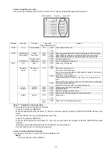
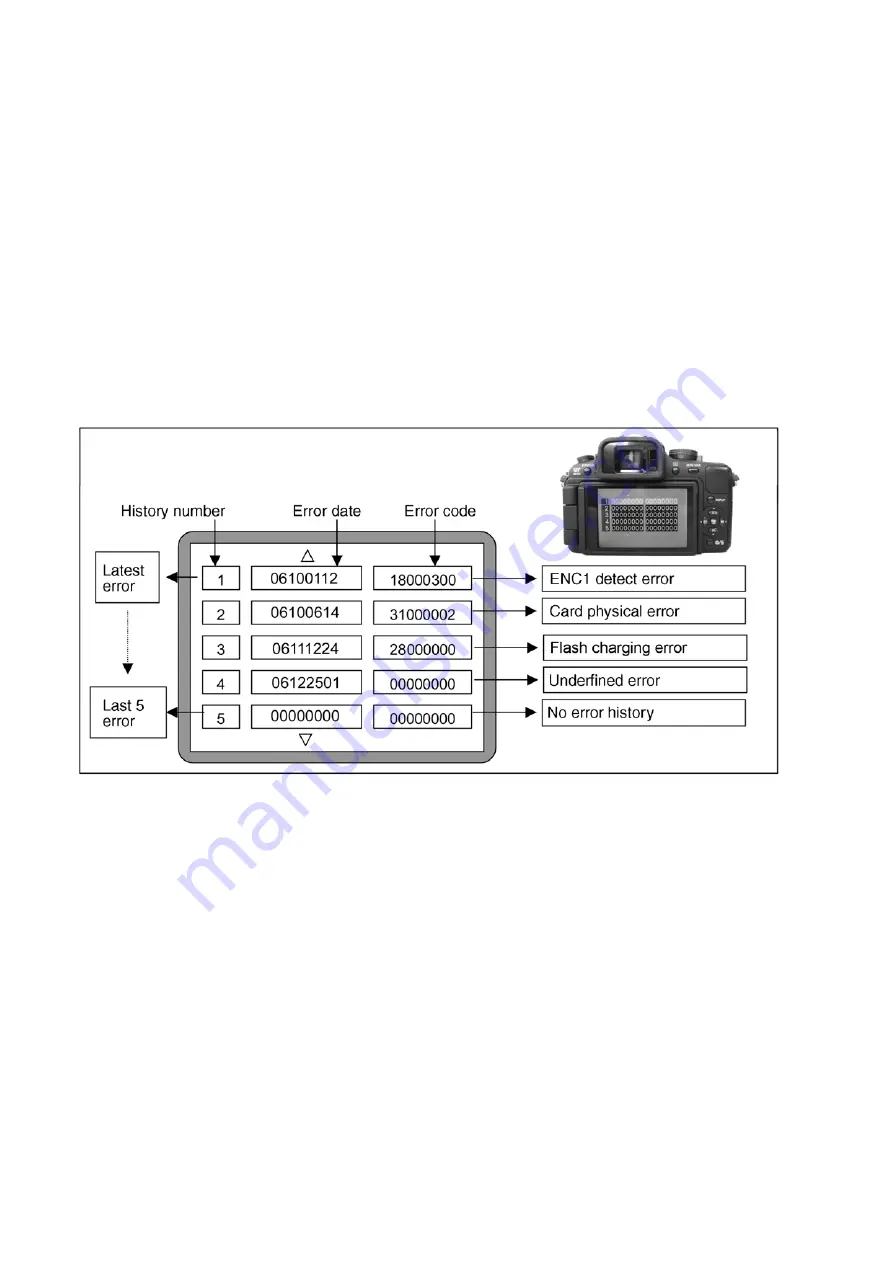
Example of Error Code Display
•
3. The change of display:
The error code can be memorized 16 error codes in sequence, however it is displayed 5 errors on the LCD.
Display can be changed by the following procedure:
“[ UP ] or [ DOWN ] of Cursor buttons” : It can be scroll up or down one.
“[ LEFT ] or [ RIGHT ] of Cursor buttons” : It can be scroll up or down every 5 error, when the same button is pressed in twice.
(When it is pressed at once, skip two data line. When it is pressed in twice, skip three data line.)
•
4. How to read the error date:
The error date code is displayed from the left in order at the year, month, day, time.
Error date information is acquired from "Clock setting" information when the error occurs. When the clock is not setting, it is
displayed as “00000000”.
Summary of Contents for Lumix DMC-G1KEB
Page 13: ...13 4 Specifications ...
Page 36: ...36 7 Troubleshooting Guide ...
Page 37: ...37 ...
Page 38: ...38 ...
Page 42: ...42 9 Disassembly and Assembly Instructions 9 1 Disassembly Flow Chart 9 2 PCB Location ...
Page 44: ...44 9 3 1 Removal of the Rear Case Unit Fig D1 Fig D2 ...
Page 45: ...45 9 3 2 Removal of the Top Case Unit Fig D3 9 3 3 Removal of the LVF Unit Fig D4 ...
Page 46: ...46 9 3 4 Removal of the Main P C B Fig D5 9 3 5 Removal of the Front Case Unit Fig D6 ...
Page 50: ...50 Fig D15 9 3 12 Removal of the LCD TFT Unit Fig D16 ...
Page 52: ...52 ...
Page 55: ...55 11 Maintenance ...
Page 56: ...56 ...

