54
10 Measurements and Adjustments
10.1. Matrix Chart for Replaced Part and Necessary Adjustment
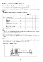
The relation between Replaced part and Necessary Adjustment is shown in the following table.
When concerned part is replaced, be sure to achieve the necessary adjustment(s).
As for Adjustment condition/procedure, consult the “Adjustment Manual” which is available in Adjustment software.
The Adjustment software is available at “TSN Website”, therefore, access to “TSN Website” at “Support Information from NWBG/
VDBG-AVC”.
NOTE:
After adjustments have been terminated, make sure to achieve “INITIAL SETTINGS”.
NOTE: (*1)
It is carried out, not only replacing the part(s)/component, but also to support customer requirement to check total performance
of the DMC-G1K in case of any mishandling, dropping or others.
NOTE: (*2)
Before replacing the MAIN PCB, proceed the EEPROM data backup from the unit.
After replacing the MAIN PCB, overwrite the EEPROM data with backup data from the unit before proceeding the adjustment /
inspection.
NOTE: (*3)
After replacing the MOUNT BOX BLOCK, the mount box data has to be stored to the unit, before proceeding the adjustment /
inspection.
For more details, consult the adjustment instruction which is available together with the Maintenance software at "software
download" on the "Support Information from NWBG/VDBG-AVC" web-site in "TSN system".
*.There is no LCD / LVF adjustment in this model.
Replaced Part
Adjustment Item
Mount Box
(*3)
Main P.C.B.
(*2)
Eye sensor Flash P.C.B.
LCD/
LVF U
Lens U/
L-Mount/
Rear Frame
Camera
Body
Section
ISO sensitivity adjustment
(ISO)
O
O
-
-
-
-
High brightness coloration
(SEN)
O
O
-
-
-
-
AWB adjustment
(WBM/WBH)
O
O
-
-
-
-
IMAGE SENSOR white scratch compensation
(WKI)
O
O
-
-
-
-
IMAGE SENSOR black scratch compensation
(BKI)
O
O
-
-
-
-
EYE SENSOR adjustment
(EYE)
-
O
O
-
-
-
Mount Box Adjustment data writing
O
-
-
-
-
-
Lens
With
Body
Resolution inspection
(*1)
O
-
-
-
-
O
Summary of Contents for Lumix DMC-G1KEB
Page 13: ...13 4 Specifications ...
Page 36: ...36 7 Troubleshooting Guide ...
Page 37: ...37 ...
Page 38: ...38 ...
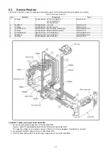
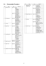
Page 42: ...42 9 Disassembly and Assembly Instructions 9 1 Disassembly Flow Chart 9 2 PCB Location ...
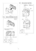
Page 44: ...44 9 3 1 Removal of the Rear Case Unit Fig D1 Fig D2 ...
Page 45: ...45 9 3 2 Removal of the Top Case Unit Fig D3 9 3 3 Removal of the LVF Unit Fig D4 ...
Page 46: ...46 9 3 4 Removal of the Main P C B Fig D5 9 3 5 Removal of the Front Case Unit Fig D6 ...
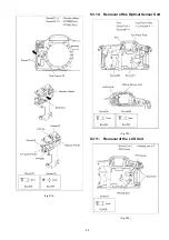
Page 50: ...50 Fig D15 9 3 12 Removal of the LCD TFT Unit Fig D16 ...
Page 52: ...52 ...
Page 55: ...55 11 Maintenance ...
Page 56: ...56 ...


