S-7
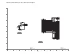
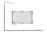
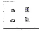
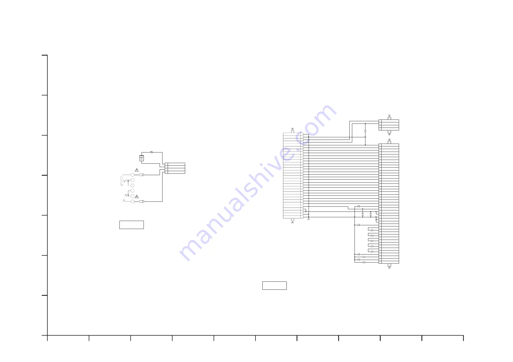
S4.5. Remote Schematic Diagram / S4.6. LCD IF Schematic Diagram
,,%%
.$
,,%%
.$
-/0$#
(2
-*&&
,-
4
%QPHKFGPVKCN
7PVKN
-<<
<$
$
/.5<6
((#4$%
$#%-A$#6
$#%-A$#6
)0&
4'/16'
)0&
#8A-';A&'6
.)-'
/.
.KVJKWO$CVVGT[
DMC-G1K
LCD IF
Schematic Diagram
%QPHKFGPVKCN
7PVKN
)
)
-/;$#
(2
%
%
(*##
%
=(*,#?
%
=(*##?
(*##
%
%
(*##
%
(*##
%
(*##
(*##
%
%
(*##
(*##
%
(*%#
%
%
(*##
(*##
%
)
)
-/0$#
(2
)
)
-/0$#
(2
%.-A.%&+(
%2
8%5
8).
8)*
8%1/
85;0%
*5;0%
&%.-
&+0
&+0
&+0
&+0
&+0
%5$
5%.
5&#
&+0
&+0
&+0
8%%
8&&+1
8&&#
%2
%2
%2
%2
%2
%2
%2
%2
%2
)0&#
)0&#
)0&
)0&
)0&
)0&
)0&
8&&
8&&
&+0
&+0
&+0
&+0
&+0
&+0
&+0
&+0
$.A/+075
0%
0%
$.A2.75
&48
.%&176
&8
&8
.%&176
.%&176
.%&176
.%&176
.%&176
.%&176
.%&176
.%&176
.%&176
.%&176
.%&176
.%&176
.%&176
.%&176
.%&176
61.%&
.%&8&
.%&*&
.%&A5%-
.%&A5&176
.%&A%5
$.
$.
)0&.%&A4'5'6
)0&56$
.%&A%.-
61.%&$#%-.+)*6
((#4$%
((#4$%
DMC-G1K
Remote
Schematic Diagram
10
9
8
7
6
5
4
3
2
1
G
F
E
D
C
B
A
Summary of Contents for Lumix DMC-G1KEB
Page 13: ...13 4 Specifications ...
Page 36: ...36 7 Troubleshooting Guide ...
Page 37: ...37 ...
Page 38: ...38 ...
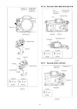
Page 42: ...42 9 Disassembly and Assembly Instructions 9 1 Disassembly Flow Chart 9 2 PCB Location ...
Page 44: ...44 9 3 1 Removal of the Rear Case Unit Fig D1 Fig D2 ...
Page 45: ...45 9 3 2 Removal of the Top Case Unit Fig D3 9 3 3 Removal of the LVF Unit Fig D4 ...
Page 46: ...46 9 3 4 Removal of the Main P C B Fig D5 9 3 5 Removal of the Front Case Unit Fig D6 ...
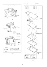
Page 50: ...50 Fig D15 9 3 12 Removal of the LCD TFT Unit Fig D16 ...
Page 52: ...52 ...
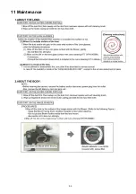
Page 55: ...55 11 Maintenance ...
Page 56: ...56 ...

