30
10 Interconnection Diagram
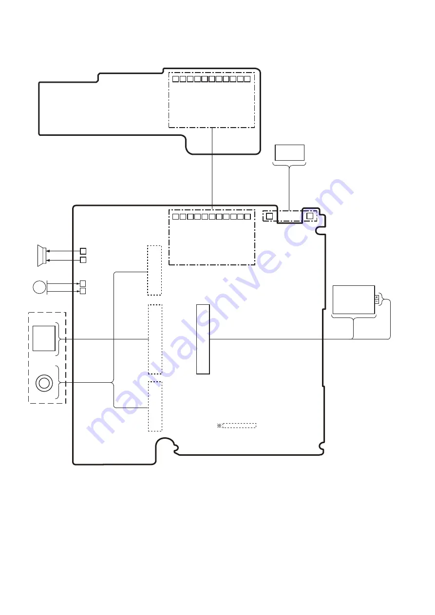
DMC-LS5 INTERCONNECTION DIAGRAM
MAIN P.C.B.
LCD UNIT
TOP P.C.B.
(COMPONENT SIDE)
: (FOIL SIDE)
BATTERY
MICROPHONE
SPEAKER
CCD
UNIT
LENS
UNIT
D GND
VP1
FLASH CHG
FLASH TRG
+3.3VS
CHARGE DONE#
KEY PWR
+3.3VD
KEY SHUT1
KEY SHUT2
D GND
D GND
VP1
FLASH CHG
FLASH TRG
+3.3VS
CHARGE DONE#
KEY PWR
+3.3VD
KEY SHUT1
KEY SHUT2
D GND
(COMPONENT SIDE)
Summary of Contents for Lumix DMC-LS6P
Page 11: ...11 4 Specifications...
Page 17: ...17 7 3 2 Removal of the Rear Case Unit Fig D3 Fig D4...
Page 18: ...18 7 3 3 Removal of the Top Case Unit Fig D5 Fig D6...
Page 19: ...19 7 3 4 Removal of the LCD Unit Fig D7 Fig D8...
Page 20: ...20 7 3 5 Removal of the Main P C B and Lens Unit W CCD Fig D9 Fig D10...
Page 31: ...Model No DMC LS6 series parts list note...
Page 32: ...Model No DMC LS6 series Frame and Casing Section...
Page 33: ...Model No DMC LS6 series Packing Parts and Accessories...


