S-10
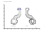
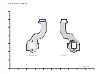
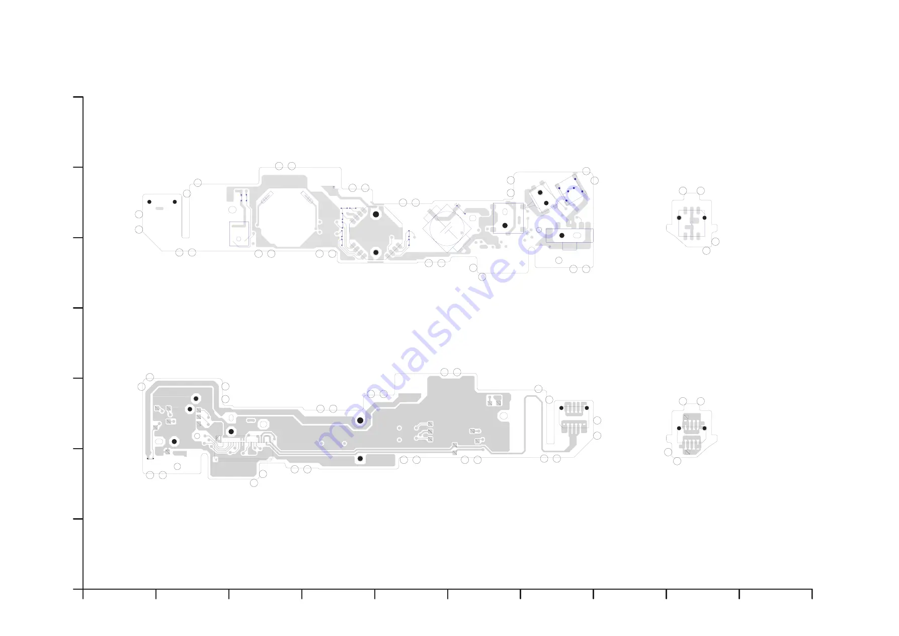
S4.2. Top Operation P.C.B. / S4.3. AF Assist P.C.B.
%.
%.
%.
%.
%.
%.
%.
%.
%.
%.
%.
%.
%.
%.
%.
%.
2
%
(2
%.
2
%.
%.
'6
4
6.
6.
5
5
5
5
5
44
4
4
4
4
4
4
/
.$
.$
'6
<$
&
&
DMC-TZ2/TZ3
Top Operation P.C.B.
(Foil Side)
(Component Side)
DMC-TZ2/TZ3
AF Assist P.C.B.
10
9
8
7
6
5
4
3
2
1
G
F
E
D
C
B
A
(Foil Side)
(Component Side)
Summary of Contents for Lumix DMC-TZ2P
Page 12: ...12 4 Specifications...
Page 13: ...13 5 Location of Controls and Components...
Page 14: ...14...
Page 22: ...22 8 Disassembly and Assembly Instructions 8 1 Disassembly Flow Chart 8 2 PCB Location...
Page 24: ...24 For DMC TZ2 Fig D1a 8 3 2 Removal of the LCD Unit For DMC TZ3 Fig D2 For DMC TZ2 Fig D2a...
Page 27: ...27 8 3 8 Removal of the Flash Unit Battery Frame Unit Lens Plate and Front Grip Fig D9 Fig D10...
Page 34: ...34 8 5 7 Assembly for the Zoom Motor Unit and Master Flange Unit...
Page 52: ...S 14...


