– A-36 –
Panasonic Corporation Electromechanical Control Business Division
industrial.panasonic.com/ac/e/
©
Panasonic Corporation 2018
AQCTB02E 201806-E
– A-37 –
Panasonic Corporation Electromechanical Control Business Division
industrial.panasonic.com/ac/e/
©
Panasonic Corporation 2018
AQCTB02E 201806-E
Temperature rise of motor
Handling instructions
Temperature rise of capacitor-run induction motor and 3-phase motor
In the case of capacitor-run induction motor, temperature rise of the motor becomes highest at no load running.
This means that the electrical loss becomes the maximum under no load condition and heat generation becomes
larger than the loss at full load. This is because of the increase of current at primary and auxiliary winding due to
the action of phase advance capacitor, and in addition to this, loss is generated to the armature by the reversed
field due to the unbalance of the current.
In the case of 3-phase motor, heat generation at no load is much smaller than that of capacitor-run induction
motor. However, temperature rise becomes larger as the load is increased due to the increase of input loss.
Operation environment standard
(1) Reference
Temperature rise of winding should be limited to:
• 75 K (deg): Japanese version
• 80 K (deg): International standard approved version
(2) Measurement method
Run the motor in the worst operation pattern (in terms of temperature rise) and measure the highest motor
frame temperature with a thermometer. The reading should be 90 ˚C or below when the ambient temperature
is 40 ˚C.
Of course, ambient temperature will become higher if ventilation is not enough. In that case, measure the
temperature at a point close to the motor.
B. Over +40˚C environment
Motor winding temperature gets very hot, and will result in deterioration of insulation and may result in
burnout. Also, lubricating grease of the bearing may leak out to shorten the life of the bearing, and may
result in the motor lock, and then result in burnout.
C. Over 85% RH environment
This may deteriorate the winding insulation. When the products are transported by air cargo or vessel and
are subjected to high temperature and humidity, pack the products in air-tight and take a necessary
treatment such as insertion of drying agents.
D. Poor-ventilation environment
Same effect may appear as the above (B) condition.
If the motor is enclosed, environmental temperature gets very high, and then may shorten the service life
drastically. Make a good ventilation environment by installing a vent so that the environmental temperature
is kept 40˚C or less.
E. Other unfavorable environment
Operation under these conditions must be avoided:
Place where the product is subjected to; dust, water/oil/coolant splash, explosive/flammable or
corrosive gas (H
2
S, SO
2
, NO
2
, Cl
2
, etc.).
(4) In the case of international standard approved model
• When using a pinion shaft motor, use it with the gear head attached.
• When using a round shaft motor, provide a means so that the heat dissipates over the machine and equipment.
Temperature rise/cooling curve and running condition
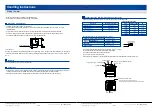
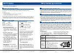
Figure 1 shows the temperature rise and cooling curve indicating relation of time lapse and motor running.
T0
: Start running
T30
: 30 minutes after starting
T
: Temperature rise saturates
T h
: Stop running
TE
: Natural cooling to the same temperature
as ambient temperature
During the time between T0 and TE, temperature q varies
as follows.
0
: Ambient temperature
30
: Temperature after 30 minutes running
: Saturated temperature
–
0 shows the temperature rise.
Typical Panasonic motors have the following time characteristics.
T
: 2.5 to 3
(h)
TE
–
T
: 3 to 4
(h)
(1) Induction motor
Induction motor is rated at continuous running, and is designed so as the temperature rise, – 0 of the
winding is lower than 75 K (deg) (in case heat resistance class is 120 (E)) or 80 K (deg) (in case 130 (B))
international standard approved model). Therefore, the temperature does not rise beyond this when it is
running continuously longer than T hours.
(2) Reversible motor
Reversible motor is 30-minute rating, and is designed so as the temperature rise, 30 – 0 of the winding
after minute running is lower than 75 K (deg). (in case heat resistance class is 120 (E)) or 80 K (deg) (in case
130 (B)) international standard approved model.
Therefore, the motor may be burned out if it is used longer than 30 minutes continuously.
(3) Special conditions
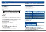
Normal working conditions for these motors are –10 ˚C to +40 ˚C, and under 85 % RH. Special attention is
required when using these motors under the following conditions A to E.
A. Under –10 ˚C environment
Output torque of the motor might be reduced since the viscosity of the grease of the gear head or motor
bearing increases. Condensation may occur when the motor is subjected to a sudden drop in the
temperature. If it occurs, rust will be generated and have an adverse effect to the service life.
Temperature (
˚C
)
30
0
T0 T30
T
TE
Time (h)
Motor size (model No.)
60 mm sq. (2.36 inch sq.) (M6.....)
70 mm sq. (2.76 inch sq.) (M7.....)
80 mm sq. (3.15 inch sq.) (M8.....)
90 mm sq. (3.54 inch sq.)
(M9
*
X.....)
(M9
*
Z.....)
Size
100 x 100 x 5 mm (3.94 x 3.94 x 0.20 inch)
120 x 120 x 5 mm (4.72 x 4.72 x 0.20 inch)
135 x 135 x 5 mm (5.31 x 5.31 x 0.20 inch)
165 x 165 x 5 mm (6.50 x 6.50 x 0.20 inch)
195 x 195 x 5 mm (7.68 x 7.68 x 0.20 inch)
Material
Aluminum
Aluminum
Aluminum
Aluminum
Aluminum
<Reference>
The table below shows size and material of heat sinks.
• Fig. 1 Temperature rise/cooling curve
*
The temperature of the winding should be 80 K (deg) or below when measured using resistance method
after rated operation with heat sink attached.

