background image

Switching Diodes

1

Publication date:  October 2007

SKF00083AED

This product complies with the RoHS Directive (EU 2002/95/EC).

Note) *: t 

=

 1 s

MA3S132DG, MA3S132EG

Silicon epitaxial planar type

For switching circuits

Features

Short reverse recovery time t

rr

Small terminal capacitance C

t

Two isolated elements contained in one package, allowing high-
density mounting

Absolute Maximum Ratings  

T

a


=

 25

°

C

Parameter

Symbol

Conditions

Min

Typ

Max

Unit

Forward voltage

V

F

I

F


=

 100 mA

1.2

V

Reverse voltage

V

R

I

R


=

 100 

µ

A

80

V

Reverse current

I

R

V

R


=

 75 V

100

nA

Terminal capacitance

MA3S132DG

C

t

V

R


=

 0 V, f 

=

 1 MHz

15

pF

MA3S132EG

2

Reverse recovery time 

*

MA3S132DG

t

rr

I

F


=

 10 mA, V

R


=

 6 V

10

ns

MA3S132EG

I

rr


=

 0.1 I

, R

L


=

 100 

3

Electrical Characteristics  

T

a


=

 25

°

±

 3

°

C

Bias Application Unit (N-50BU)

90%

Pulse Generator
(PG-10N)
R

s


50 

Wave Form Analyzer
(SAS-8130)
R

i


50 

t

p


µ

s

t

r


0.35 ns

δ = 

0.05

I

F


10 mA

V

R


6 V

R

L


100 

10%

Input Pulse

Output Pulse

I

rr


0.1 I

R

t

r

t

p

t

rr

V

R

I

F

t

t

A

Note) 1. Measuring methods are based on JAPANESE INDUSTRIAL STANDARD JIS C 7031 measuring methods for diodes.

2. Absolute frequency of input and output is 100 MHz.

3. *: t

rr

 measurement circuit

1

2

3

1

3

2

Parameter

Symbol

Rating

Unit

Reverse voltage

V

R

80

V

Maximum peak reverse voltage

V

RM

80

V

Forward current

Single

I

F

100

mA

Double

150

Peak forward

Single

I

FM

225

mA

current

Double

340

Non-repetitive peak

Single

I

FSM

500

mA

forward surge current 

*

Double

750

Junction temperature

T

j

150

°

C

Storage temperature

T

stg

55 to 

+

150

°

C

D

E

Package

Code
SSMini3-F3

Pin Name

MA3S132DG

MA3S132EG

1: Cathode 1

1: Anode 1

2: Cathode 2

2: Anode 2

3: Anode

3: Cathode

Marking Symbol

MA3S132DG: MO

MA3S132EG: MU

Internal Connection

Summary of Contents for MA3S132DG

Page 1: ...a 25 C 3 C Bias Application Unit N 50BU 90 Pulse Generator PG 10N Rs 50 Ω Wave Form Analyzer SAS 8130 Ri 50 Ω tp 2 µs tr 0 35 ns δ 0 05 IF 10 mA VR 6 V RL 100 Ω 10 Input Pulse Output Pulse Irr 0 1 IR tr tp trr VR IF t t A Note 1 Measuring methods are based on JAPANESE INDUSTRIAL STANDARD JIS C 7031 measuring methods for diodes 2 Absolute frequency of input and output is 100 MHz 3 trr measurement c...

Page 2: ...120 1 10 102 103 104 Reverse voltage VR V Reverse current I R nA Ta 150 C 100 C 25 C 0 0 4 0 8 1 2 1 6 40 0 40 80 120 160 200 Ambient temperature Ta C Forward voltage V F V IF 100 mA 10 mA 3 mA 10 1 40 0 40 80 120 160 200 1 10 102 103 104 Ambient temperature Ta C Reverse current I R nA VR 75 V 35 V 6 V 0 2 4 6 8 0 20 40 60 80 100 120 Reverse voltage VR V Terminal capacitance C t pF f 1 MHz Ta 25 C...

Page 3: ... 103 104 105 Reverse voltage VR V Reverse current I R nA Ta 150 C 100 C 25 C 0 0 4 0 8 1 2 1 6 40 0 40 80 120 160 200 Ambient temperature Ta C Forward voltage V F V IF 100 mA 10 mA 3 mA 1 40 0 40 80 120 160 200 10 102 103 104 105 Ambient temperature Ta C Reverse current I R nA VR 75 V 35 V 6 V 0 1 2 1 0 0 8 0 6 0 4 0 2 0 20 40 60 80 100 120 Reverse voltage VR V Terminal capacitance C t pF f 1 MHz ...

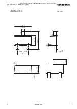
Page 4: ...0083AED This product complies with the RoHS Directive EU 2002 95 EC SSMini3 F3 Unit mm 1 00 0 05 0 50 0 50 1 60 0 05 0 03 0 26 0 05 0 02 1 2 3 0 85 0 05 0 03 1 60 0 05 0 70 0 05 0 03 0 to 0 10 5 0 45 0 13 0 05 0 02 0 375 0 05 5 ...

Page 5: ...ard applications intended 4 The products and product specifications described in this book are subject to change without notice for modification and or im provement At the final stage of your design purchasing or use of the products therefore ask for the most up to date Product Standards in advance to make sure that the latest specifications satisfy your requirements 5 When designing your equipmen...

Reviews: