13
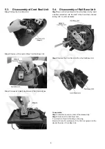
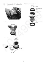
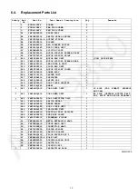
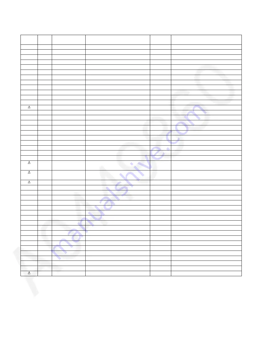
6.4.
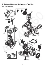
Replacement Parts List
MMH1205
Safety
Ref.
No.
Part No.
Part Name & Description
Qty
Remarks
1
XTN4+10FFX
SCREW
2
2
XTN4+12BFJ
PAN TAP SCREW
1
3
XTN4+16BFJ
PAN TAP SCREW
6
B1
YMV02ADN000
UPPER BODY
1
B2
YMV08EDP000
SWITCH PEDAL SPRING
2
B3
YMV30LDQ000-P
OUTLET FILTER
1
B4
YMV01DDN000
BUCKLE
1
B5
YMV46HBW000
BAG CLAMPER SPRING
1
B6
YMV92LDQ0K0
DUST COVER UNIT
1
B7
YMV0NAAR000
SILICON CLOTH
1
B8
YMV02FDP000
MOTOR SUPPORT RUBBER FRONT
1
B9
YMV07FDP000
MOTOR SUPPORT FRONT
1
B10
YMV92FAR10C
MOTOR FAN UNIT
1
(CDS) 1400W 240V
B11
YMV03FDN000
MOTOR SUPPORT RUBBER REAR
1
B12
YMV68VDP000
LEAD WIRE B UNIT
1
B13
YMV99KDN000
CLOTH BAG UNIT
1
B14
YMV63FDN000
MOTOR SUPPORT COVER
1
B15
YMV03ADN000
LOWER BODY
1
B16
YMC95C7K100
CASTER UNIT
1
B17
YMV23KBW000
SUPPORTER
1
B18
YMV25QDN000
SWIVEL CAP
1
B19
YMV66KDN000
DUST COVER PACKING
1
B20
YMV01CAQ080
WHEEL 2
B21
YMV99NDQ00C
CORD REEL UNIT
1
C3 PLUG (SD2, KUWAIT, NIGERIA
AND UAE)
B21
YMV99NDQ000
CORD REEL UNIT
1
E2 PLUG (GENERAL MIDDLE EAST,
PGF, EGYPT AND AFRICA GENERAL)
B22
YMV96ADN000
BODY PARTITION UNIT
1
B23
YMV05EDN000
SWITCH PEDAL
1
B24
YMV46NDN000
BRAKE PEDAL
1
B25
YMV92ADQ0K0
BODY COVER UNIT
1
B26
YMV99M4W100
INDICATER UNIT
1
B27
YMV64HBW000
SUCTION INLET PACKING
1
B28
YMV25KDN000
DUST BOX PLATE
1
B29
YMC37KKK000
SECONDARY FILTER
1
A1
YMV99PBA000
METAL EXTENSION WAND
2
A2
YMV98PDN000
CURVE WAND UNIT
1
A3
YMV27HBW000
CONNECTION WAND
1
A4
YMV76PDN000
NOZZLE HOLDER
1
A5
YMV60R9L080
CREVICE NOZZLE
1
A6
YMC99RXQ100
FLOOR NOZZLE ASS'Y
1
A7
YMC84PXP200-P
HOSE UNIT
1
A8
YMC88RYX080
DUSTING BRUSH UNIT
1
P1
YMV61ZDQ000
CARTON BOX
1
P2
YMV98ZDN000
CUSHION UNIT
1
YMV01ZDN000
INSTRUCTION BOOK
1
Summary of Contents for MC-CG523K147-AE
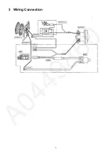
Page 3: ...3 3 Wiring Connection ...
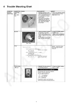
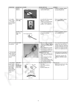
Page 4: ...4 4 Trouble Shooting Chart ...
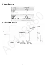
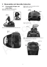
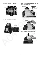
Page 5: ...5 ...
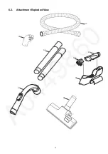
Page 11: ...11 6 2 Attachment Exploded View A7 A8 A5 A4 A6 A2 A3 A1 ...