background image

4

4 Trouble Shooting Chart

Summary of Contents for MC-CG523K147-AE

Page 1: ...AND UAE GEN ERAL MIDDLE EAST PGF EGYPT AND AFRICA GENERAL TABLE OF CONTENTS PAGE PAGE 1 Specifications 2 2 Schematic Diagram 2 3 Wiring Connection 3 4 Trouble Shooting Chart 4 5 Disassembly and Assembly Instruction 6 5 1 Disassembly of Upper and Lower Body 6 5 2 Disassembly of Motor Case Set 7 5 3 Disassembly of Cord Reel Unit 8 5 4 Disassembly of Rail Base Unit 8 5 5 Disassembly of Fan Motor Unit...

Page 2: ...IEC 1150 1350W Power Control SLIDE Dust Capacity 3 0L Automatic Cord Rewind 0 Vac Gauge 0 Exhaust Filter NORMAL Extension Wands METAL EXTENSION WAND Blower Operation 0 Floor Nozzle 2 STEP Dust Bag CLOTH BAG Dimension H x W x L mm 240mm X 304mm X 450mm Net Weight 4 5 KG Cord Length 5 0 M Cleaning Tools CREVICE TOOL DUSTING BRUSH ...

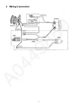
Page 3: ...3 3 Wiring Connection ...

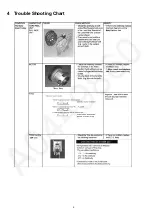
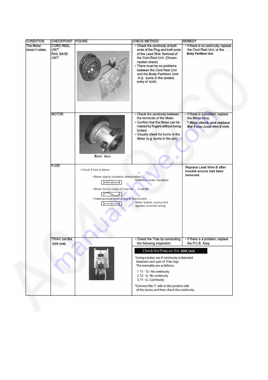
Page 4: ...4 4 Trouble Shooting Chart ...
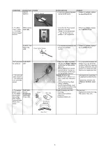
Page 5: ...5 ...

Page 6: ...ove Dust Bag Step 2 Release Dust Cover from Hanger Step 3 Remove 2 screws from the Front Side of the body Step 4 Release 2 catches using philip screwdriver Step 5 Remove Body Cover Step 6 Take out the filter Step 7 Release 4 catches using philip screwdriver to take out the Cord Rewind pedal and Switch pedal ...

Page 7: ...om back side of body Step 9 Take out Upper Body from Lower Body 5 2 Disassembly of Motor Case Set Step 1 Pull out the switch on off Step 2 Remove Volume Ass y from Motor Case Set Step 3 Pull up the Motor Case Set from Lower Body ...

Page 8: ...Reel Unit from Rail base Unit by insert a slotted screwdriver into the shaft of the Cord Reel Unit and turning it 90 counter clockwise Step 2 Remove the Cord Reel Unit from the Rail Base Unit To assemble Step 1 Assemble in reverse order of the disassembly Step 2 Pretension the Cord Reel Unit Turn the Cord Reel Unit holding on the plug Number of turns for pretension of the Cord is engraved on the s...

Page 9: ...9 5 5 Disassembly of Fan Motor Unit Step 1 Pull up Motor Set Step 2 Remove the Silicon Cloth Step 3 Disconnect 2 Wire Terminals Step 4 Remove Motor Support Rubber ...

Page 10: ...ploded View and Replacement Parts List 6 1 Exploded View B26 B28 B27 B23 B25 B3 B21 B11 B9 B10 B8 B13 B15 B20 B17 B5 B19 1 B24 B29 B20 B2 2 3 3 3 3 3 B2 B1 B18 B22 Plug 3 B16 B7 B12 1 B14 B4 B6 Plug C3 Plug E2 ...

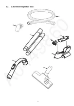
Page 11: ...11 6 2 Attachment Exploded View A7 A8 A5 A4 A6 A2 A3 A1 ...

Page 12: ...12 6 3 Packing Instruction HOSE UNIT CONNECTION WAND CURVED WAND COMPLETE SET FLOOR NOOZLE ASS Y DUSTING BRUSH UNIT CREVICE NOZZLE NOZZLE HOLDER P1 P2 P2 METAL EXTENSION WAND ...

Page 13: ...CASTER UNIT 1 B17 YMV23KBW000 SUPPORTER 1 B18 YMV25QDN000 SWIVEL CAP 1 B19 YMV66KDN000 DUST COVER PACKING 1 B20 YMV01CAQ080 WHEEL 2 B21 YMV99NDQ00C CORD REEL UNIT 1 C3 PLUG SD2 KUWAIT NIGERIA AND UAE B21 YMV99NDQ000 CORD REEL UNIT 1 E2 PLUG GENERAL MIDDLE EAST PGF EGYPT AND AFRICA GENERAL B22 YMV96ADN000 BODY PARTITION UNIT 1 B23 YMV05EDN000 SWITCH PEDAL 1 B24 YMV46NDN000 BRAKE PEDAL 1 B25 YMV92AD...

Reviews: