7
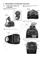
5 Disassembly and Assembly Instruction
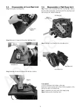
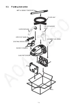
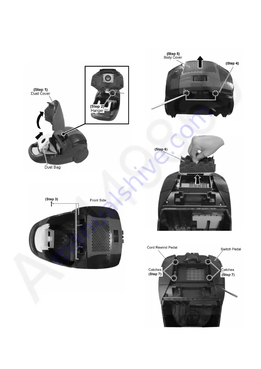
5.1.
Disassembly of Upper and
Lower Body
Step 1
Open Dust Cover & remove Dust Bag.
Step 2
Release Dust Cover from Hanger.
Step 3
Remove 2 screws from the Front Side.
Step 4
Release 2 catches using Philip Screwdriver.
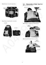
Step 5
Remove Body Cover.
Step 6
Take out Filter (sponge)
Step 7
Release 4 catches to take out the pedal.
Summary of Contents for MC-CG525R147-AE
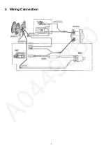
Page 4: ...4 3 Wiring Connection ...
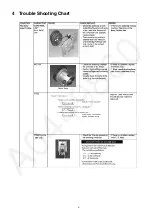
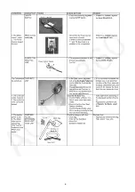
Page 5: ...5 4 Trouble Shooting Chart ...
Page 6: ...6 ...
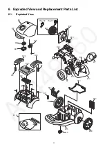
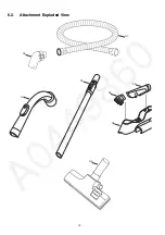
Page 12: ...12 6 2 Attachment Exploded View A7 A8 A5 A4 A6 A1 A2 A3 ...