8
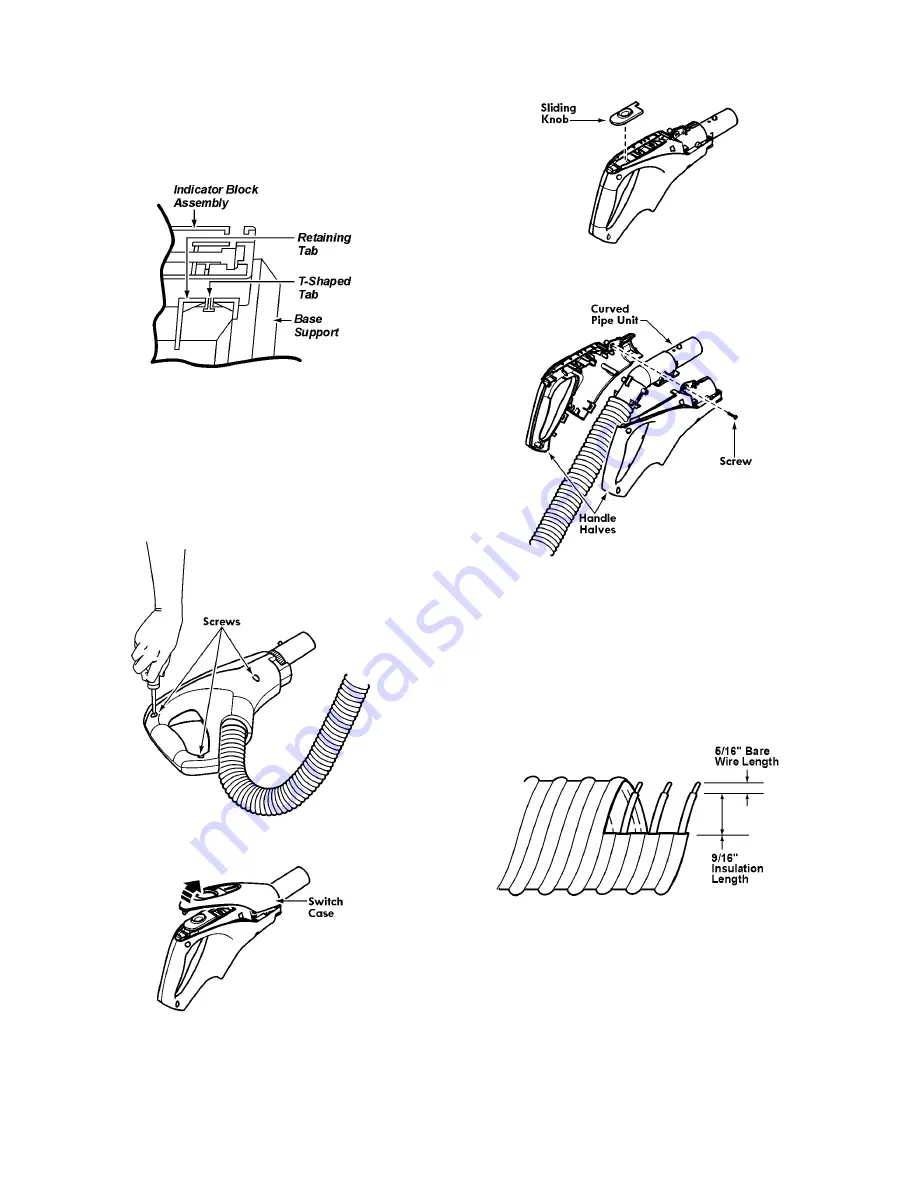
4. Install indicator block assembly. Holding the assembly at
a slight angle, insert the edge of the part behind the
retaining tabs (use T-shaped tab on assembly to align in
slot of retaining tab). With fingers lifting base off the floor
(to free front axle) use both thumbs to push the indicator
block assembly down until it snaps in place.
5. Replace overload protector into pocket in ribs.
6. Replace remaining parts (see NOZZLE COVER and
BELT & AGITATOR).
2.8.
Hose Handle
2.8.1.
Removal
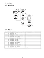
1. Remove three (3) screws from hose handle.
2. Remove the switch case.
3. Remove sliding knob.
4. Remove one (1) screw and separate handle halves.
5. Remove hose wires from retainers on curved pipe unit
and unplug wire connectors.
6. Pull hose from curved pipe unit.
2.8.2.
Reinstallation
1. If hose is being replaced, cut and strip wires on both ends
of new hose, using wire strippers.
NOTE: Refer to wiring diagram.


