background image

3.1. Lower Plate Replacement

3.1.1. Removal

 1. Before servicing any parts, disconnect vacuum from

electrical outlet.

 2. Place paper under nozzle whenever lower plate is removed

to protect floor.

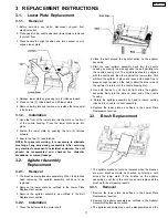
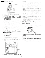
 3. Place handle in upright position and turn vacuum over to

expose lower plate.

 4. Release lower plate by pressing two (2) latches inward.
 5. Press on two (2) tabs inward and lift lower plate.
 6. Remove lower plate and remove any residue that may exist

in belt area.

3.1.2. Installation

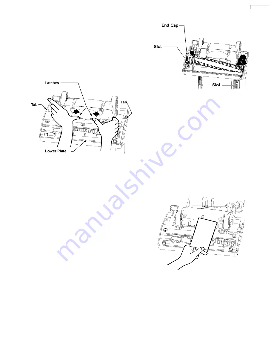
 1. Hook the front of the lower plate into the slots on the front

of the nozzle housing. Press the lower plate down into
place.

 2. Fasten the lower plate by pushing the two (2) latches

outward.

 3. Ensure the two (2) tabs latched.

NOTE: For general servicing, it is necessary to eliminate
pinching of any wire during reassembly. After servicing
any electrical component or electrical enclosure, the unit
should be reassembled and checked for dielectric
breakdown or current leakage.

3.2. Agitator Assembly

Replacement

3.2.1. Removal

 1. The brushes are replaceable separately. When the brushes

need replacing, the agitator assembly will have to be
removed.

 2. Remove the lower plate as outlined in the Lower Plate

Replacement section.

 3. Remove the agitator assembly as outlined in the Belt

Replacement section. .

3.2.2. Installation

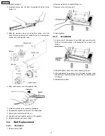
 1. Place the belt around the motor shaft.

 2. Place the belt around the agitator pulley on the agitator

assembly.

 3. Start the new agitator assembly back into the nozzle

housing by placing the side opposite the belt partially into
the nozzle housing slot. The small tabs should be aligned
with the nozzle and the other against the lower plate. This
will hold the agitator in place and leave both hands free to
place enough tension on the belt to allow the other side of
the agitator to return into the nozzle housing slot.

 4. Use both hands to pull the belt tight, slide the agitator

assembly firmly into the slots on each end of the nozzle
housing.

 5. Rotate the agitator assembly by hand to insure nothing

rubs and to check for correct assembly.

 6. Replace the lower plate as outlined in the Lower Plate

Replacement section.

3.3. Brush Replacement

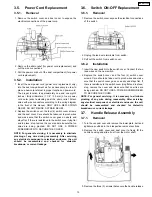
 1. The agitator brushes should be replaced when the brushes

are worn. Brushes should be checked by holding a card
across the lower plate. If the bristles on the agitator
assembly do not touch the card you should replace all the
brushes for best cleaning results.

3.3.1. Removal

 1. Remove the lower plate as outlined in the Lower Plate

Replacement section.

 2. Remove the agitator assembly as outlined in the Agitator

Assembly Replacement section.

 3. The agitator assembly may now be disassembled and the

3 REPLACEMENT INSTRUCTIONS

11

MC-GG773-00

Summary of Contents for MC-GG773-00

Page 1: ...C HOME APPLIANCES COMPANY DIVISION OF PANSONIC CORPORATION OF NORTH AMERICA All rights MC GG773 00 Vacuum Cleaner Specifications are subject to change without notice for further improvement Order Number MAC0712002CE ...

Page 2: ... 4 Packing Materials 10 3 REPLACEMENT INSTRUCTIONS 11 3 1 Lower Plate Replacement 11 3 2 Agitator Assembly Replacement 11 3 3 Brush Replacement 11 3 4 Belt Replacement 12 3 5 Power Cord Replacement 13 3 6 Switch ON OFF Replacement 13 3 7 Handle Release Assembly 13 3 8 Motor Replacement 14 3 9 Motor Protector Replacement 14 CONTENTS Page Page 2 MC GG773 00 ...

Page 3: ...1 WIRING DIAGRAM AND DRAWING 1 1 Wiring Diagram 3 MC GG773 00 ...

Page 4: ...ervicing it is necessary to eliminate pinching of any wire during reassembly After servicing any electrical component or electrical enclosure the unit should be reassembled and checked for dielectric breakdown or current leakage 4 MC GG773 00 ...

Page 5: ...2 EXPLODED VIEW AND PARTS LIST 2 1 Body 2 1 1 Exploded View 5 MC GG773 00 ...

Page 6: ...MPELLER 1 30 AC90FDEKZ000 MOTOR ASSEMBLY 1 31 AC26FDDWZU01 MOTOR CAP 1 32 AC45LDDWZV07 AIR OUTLET PACKING 2 33 AC99GAMMZ00 NOISE SUPPRESSOR 1 34 AC69KJMZV06 PROTECTOR 1 35 AC70KCNFZG00 PROTECTOR SPRING 1 36 AC68KAJDZV06 PROTECTOR CASE 1 37 AC39GDDXZ000 GREEN LEAD WIRE UNIT 1 38 AC25SBSKZ000 FLANGE 1 39 AXTN4 8JFY SCREW TAPTITE 2 Shipped 10 per package 40 AC03FAFYZ00 MOTOR SUPPORT RUBBER 1 41 AC39A...

Page 7: ...2 2 Nozzle Housing 2 2 1 Exploded View 7 MC GG773 00 ...

Page 8: ...ER 1 9 AC19ACPSZ000 BODY PACKING 1 10 AC34PDDEZV06 NOZZLE HOSE 1 11 AC92SDDXZ000 AGITATOR ASSEMBLY 1 12 AC85RDDWZU01 BRUSH UNIT 6 13 AC01ADEKZYU2 BODY NOZZLE HOUSING 1 14 AC10ADDWZV07 FURNITURE GUARD 1 15 AMC68A V30 SCREW FOR BODY 2 16 AC91ADDXZV07 LOWER PLATE UNIT 1 17 AC43AAFYZ00 BRACKET 1 18 AC47ADAAZM0E PEDAL 1 19 AC58AAFVZ00 PEDAL SPRING 1 20 AMC51A YUZ0000 PEDAL SHAFT 1 21 AXTN4 16BFY SCREW ...

Page 9: ... 3 2 Parts List Handle Ref No Part No Part Name Description Quantity Remarks 1 AC93BDDXZV07 HANDLE GRIP UNIT 1 2 AC06BDDXZV07 HANDLE COVER A 1 3 AC07BDDWZV07 HANDLE COVER B 1 4 AXTN4 16BFY SCREW 5 Shipped 10 per package 9 MC GG773 00 ...

Page 10: ...Packing Materials 2 4 1 Exploded View 2 4 2 Parts List Packing Materials Ref No Part No Part Name Description Quantity Remarks 1 AC61ZDEKZ000 Packing Assembly 1 Includes 1 and items a thru g 10 MC GG773 00 ...

Page 11: ... the Belt Replacement section 3 2 2 Installation 1 Place the belt around the motor shaft 2 Place the belt around the agitator pulley on the agitator assembly 3 Start the new agitator assembly back into the nozzle housing by placing the side opposite the belt partially into the nozzle housing slot The small tabs should be aligned with the nozzle and the other against the lower plate This will hold ...

Page 12: ...ut 10 Position belt over agitator pulley on the agitator 11 Reinstall agitator and lower plate 3 4 Belt Replacement 3 4 1 Removal 1 Remove lower plate 2 Remove agitator by carefully lifting out 3 Remove worn or broken belt 4 Clean agitator 3 4 2 Installation 1 Loop new belt Panasonic Type UB8 only around motor shaft and agitator pulley see illustration for correct belt routing 2 Reinstall agitator...

Page 13: ...any wire during reassembly After servicing any electrical component or electrical enclosure the unit should be reassembled and checked for dielectric breakdown or current leakage 3 6 Switch ON OFF Replacement 3 6 1 Removal 1 Remove the switch cover expose the electrical connections of the switch 2 Unplug the lead wire terminals from switch 3 Pull out the switch from switch cover 3 6 2 Installation...

Page 14: ...t the motor leads and remove the motor assembly 4 Remove two air outlet packing and two screws from the motor assembly to open 5 Remove noise suppressor motor cap and motor flange Save these items to place them on the new motor 3 8 2 Installation 1 Add a new seal impeller and body packing to the new motor 2 Assemble the noise suppressor motor cap and motor flange onto new motor and place it into t...

Reviews: