background image

© 2015 Panasonic Manufacturing Malaysia Berhad
(6100-K). Unauthorized copying and distribution is a
violation of law.

PMMA151141CE

Vacuum Cleaner

Model No.

MC-YL637S147-AE

MC-YL637S149-AE

MC-YL637S149-EG

MC-YL637S149-JO

MC-YL637S149-LB

MC-YL637S149-LY

MC-YL637S149-OM

MC-YL637S149-QA

MC-YL637S747-KW

MC-YL637S747-NG

MC-YL637S747-SA

Destination : 

UAE, Egypt, Jordan, Lubnan, Libya, 
Oman, Qatar, Kuwait, Nigeria, Saudi 
Arabia

Summary of Contents for MC-YL637S147-AE

Page 1: ...ion of law PMMA151141CE Vacuum Cleaner Model No MC YL637S147 AE MC YL637S149 AE MC YL637S149 EG MC YL637S149 JO MC YL637S149 LB MC YL637S149 LY MC YL637S149 OM MC YL637S149 QA MC YL637S747 KW MC YL637S747 NG MC YL637S747 SA Destination UAE Egypt Jordan Lubnan Libya Oman Qatar Kuwait Nigeria Saudi Arabia ...

Page 2: ...isassembly of Lower Body 4 4 2 Disassembly of Body Cover 4 4 3 Disassembly of Main Switch 5 4 4 Disassembly of Motor 6 4 5 Disassembly of Rail Base Unit 7 5 Trouble Shooting Chart 8 6 Exploded View and Replacement Parts List 9 6 1 Exploded View 9 6 2 Attachment Exploded View 10 6 3 Packing Instruction 11 6 4 Replacement Parts List 12 ...

Page 3: ...orial Diagram 3 Schematic Diagram Model MC YL637 Series Power Source 220 240V 50 60Hz In Power Max 2300W In Power IEC 1550 1800W Dimensions L x W x H mm 363mmX353mmX594mm Nett Weight kg 6 2 kg Dust Capacity L 21L Cord Length 8m ...

Page 4: ... 1 Disassembly of Lower Body Step 1 Release 2 Buckles Step 2 Take out Body Cover from Lower Body 4 2 Disassembly of Body Cover Refer to Disassembly of Lower Body Step 1 Remove 4 screws from Upper Body Step 2 Take out Body Cover from Upper Body ...

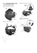
Page 5: ...isassembly of Body Cover Refer to Disassembly of Lower Body Step 1 Remove 2 screws from Body Cover Step 2 Take out Handle from Body Cover Step 3 Push down Main Switch from Body Cover Step 4 Release 2 Wire Connectos Step 5 Remove Main Switch Assy ...

Page 6: ...sassembly of Body Cover Refer to Disassembly of Lower Body Step 1 Take up Motor and Rail Base Unit from Upper Body Step 2 Release 2 Wire Connectors from Rail Base Unit Step 3 Take out Silicon Cloth Step 2 Release Wire Connectors from Motor ...

Page 7: ...to Disassembly of Lower Body Refer to Disassembly of Motor Step1 Step2 Step 1 Remove the Cord Reel Unit from the Rail Base Unit by insert a slotted screwdriver into the shaft of the Cord Reel Unit and turning it 90 anti clockwise Step 2 Remove Cord Reel Unit from Rail Base Unit ...

Page 8: ...8 5 Trouble Shooting Chart ...

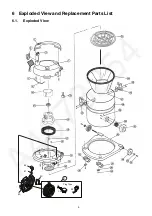
Page 9: ...9 6 Exploded View and Replacement Parts List 6 1 Exploded View 41 11 Plug Type E2 C3 42 40 43 ...

Page 10: ...10 6 2 Attachment Exploded View A11 ...

Page 11: ...11 6 3 Packing Instruction ...

Page 12: ...00 BUCKLE UNIT 2 27 YMV32D81000 BUCKLE KNOB 2 28 YMV97ALD0S0 BA LOWER BODY UNIT 1 29 XTT35 16BFJ TRUSS TAP SCREW 3 30 YMV50KLD000 VALVE GRAMMET 1 31 YMV01HLD0K0 FRONT COVER 1 32 XTN4 16BFJ PAN TAP SCREW 2 33 YMV05CLD0K0 WHEEL CAP 2 34 YMV01CFP0V0 WHEEL 2 36 YMC43ADE0K0 FRAME 1 37 YMC95C0E1H0 CASTER UNIT 2 38 YMC26CB0100 WASHER 2 39 XTN4 16BFJ PAN TAP SCREW 2 40 YMV94NLD000 BREAK LEVER UNIT 1 41 YM...

Reviews: