Inverter signal
(1)
Outline
In this model, an inverter is used for compressor control. In order to investigate the status of the
compressor and the inverter, signal verification of the inverter side is necessary.
(2)
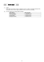
The error signal on the inverter side is as follows.
Failure Mode
LED operation
Normal operation
1 blink each 15 s
Thermostat failure
2 blinks each 5 s
Inverter failure
3 blinks each 5 s
Compressor failure
4 blinks each 5 s
-33-
Summary of Contents for MDF-DU502VH
Page 8: ...Dimension MDF DU502VH 5 ...
Page 9: ...MDF DU702VH 6 ...
Page 17: ...Wiring Diagram 14 ...
Page 18: ...main Circuit Diagram 15 ...
Page 19: ...power 16 ...
Page 20: ...USB 17 ...
Page 73: ...WIRING YG Y Y GR B G W W W Y G R BL Y W R R BL R OR B BL R OR B Y W Y G Y G R BL 70 ...


