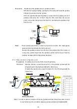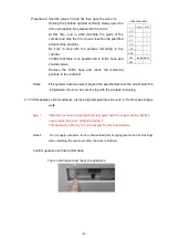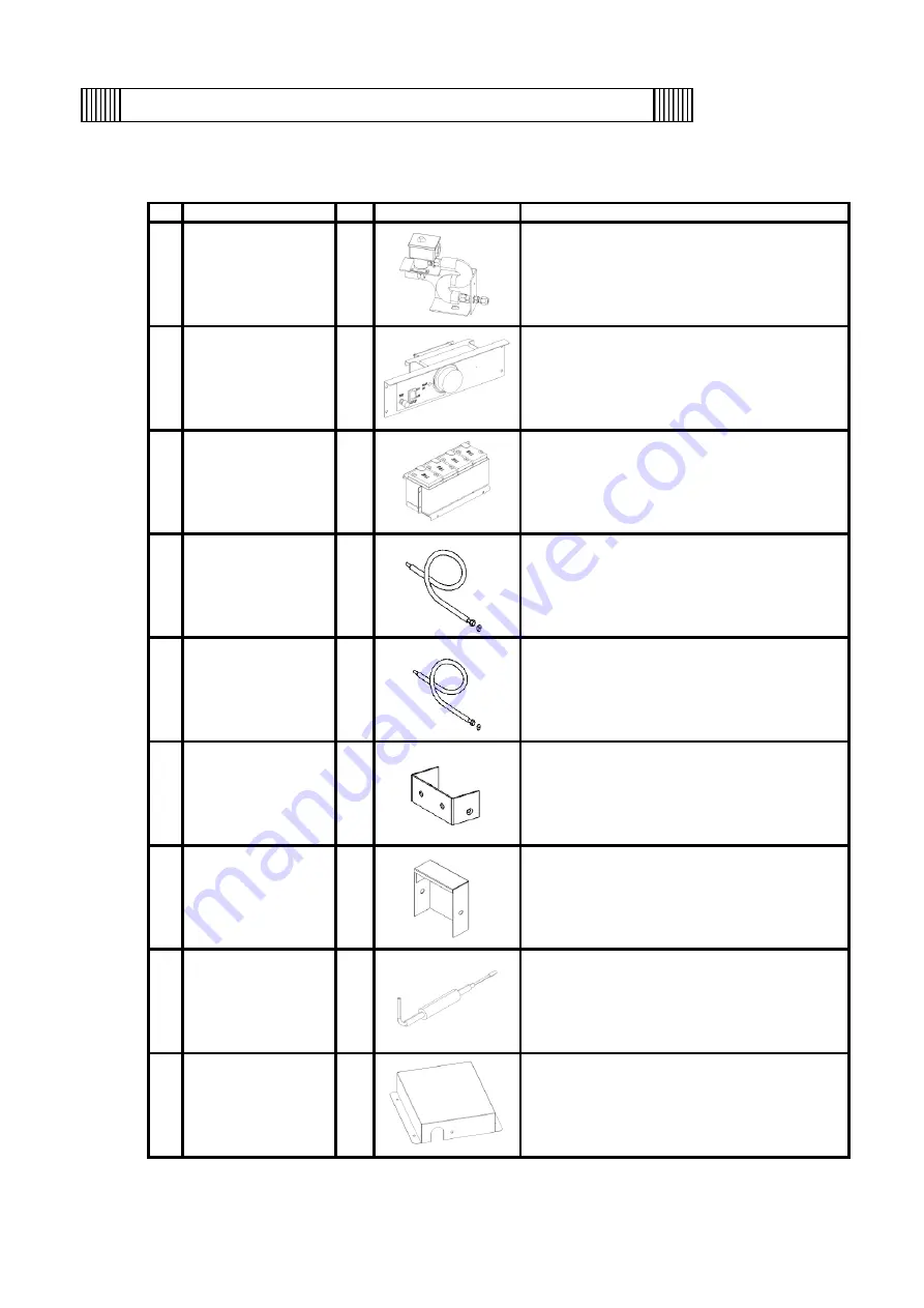
Confirmation of packing items
①
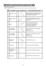
Table 1
No.
PARTS NAME
Q'TY.
APPEARANCE
THE EXPLANATION OF THE USE
1
CO2 solenoid valve
Assy.
1
Electromagnetic valve for injecting the LCO
2
gas into the freezer chamber (put together
at the installation of MDF-UB7).
2
Back-up cooling kit
body
1
For controlling the LCO
2
gas injection to
prevent the temperature rise in the event of
power failure.
3
Battery
1
Power source for backup board.
※
Never touch the terminal portion.
That may cause electric shock.
DC 6 V x 4 pcs. = DC 24 V
4
Connecting pipe
and joint packing
1
Pipe for connecting the LCO
2
gas cylinder
with pipe joint.
※
Metric screw type
5
Connecting pipe
and joint packing
1
Pipe for connecting the LCO
2
gas cylinder
with pipe joint.
※
Inch screw type
6
Nozzle cover
attachment
1
For fixing the nozzle cover.
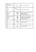
7
Nozzle cover
1
To protect the nozzle in the chamber.
8
CO2 injection
nozzle and thermal
insulation
1
Component for CO
2
solenoid valve assy.
9
Solenoid cover
1
To protect the CO
2
solenoid valve assy.
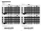
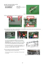
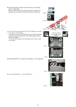
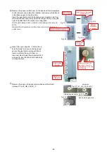
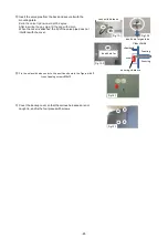
Before installing the optional component, check the accessories listed in table 1 below are enclosed.
Backup cooling kit installation and setting procedure
-64-
Summary of Contents for MDF-DU702VH
Page 8: ...Dimension MDF DU502VH 5 ...
Page 9: ...MDF DU702VH 6 ...
Page 17: ...Wiring Diagram 14 ...
Page 18: ...main Circuit Diagram 15 ...
Page 19: ...power 16 ...
Page 20: ...USB 17 ...
Page 73: ...WIRING YG Y Y GR B G W W W Y G R BL Y W R R BL R OR B BL R OR B Y W Y G Y G R BL 70 ...

