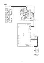
INSTALLATION
4. When no leakage is found, close the cylinder valve.
10. Close all of the cylinder valve and also the cylinder stand valve.
11. Check the injection by following the procedure in the “Injection Test” on the next page.
INJECTION TEST
1. Run the freezer until the chamber temperature reaches the appropriate level.
Note the backup cooling time is decrease if the liquid CO2 gas is injected continuously.
●
Refer to the “Operating Instructions” for an explanation of the switches on the freezer.
2. Connect the valve on the CO
2
cylinder stand with the CO
2
outlet of the cylinder with a flexible hose.
2. With the power switch of the backup cooling kit turned off, open the cylinder valve and the cylinder stand valve.
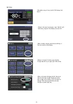
3. Set the temperature of the backup cooling kit to a temperature 10
℃
or more higher than the freezer chamber temperature.
4. Turn on the power switch of the backup cooling kit with the freezer door closed.
For the up-right freezer, check the indicator lamp (green ) on the door switch is ON.
8. Connect the other side of the connecting pipe with the cylinder
valve (when 1 cylinder) or the cylinder stand valve (when more
than 1 cylinder). Tighten the flared nut all the way.
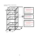
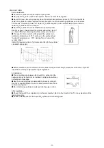
Note: Run the connecting pipe in a coil or U-bend formation to act
as a cushion (see Fig. 2).
Note:
The temperature setting range of the backup cooling kit is between
-
50 and
-
70
℃
. The consumption of liquid CO
2
gas is increased and the backup cooling time is decreased considerably if the set temperature is lower than
-
70
℃
.
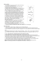
9. Open the cylinder valve or cylinder stand valve (whichever
applicable) and check for leakage at the both ends of the
connecting pipe. The leakage can be checked by applying soapy
water to the connecting area as shown in Fig. 3.
5. Press the test switch for the backup cooling kit to check the liquid CO
2
gas is injected into the freezer chamber.
6. If the set temperature of the backup cooling kit is below
-
60
℃
, turn off the power switch of the freezer.
7. Check the liquid CO
2
gas is injected into the freezer chamber automatically when the chamber temperature rises.
8. Ensure the injection of the liquid CO
2
gas automatically stops when the chamber temperature goes down.
With the back-up system set in this way, the liquid CO
2
gas is injected into the freezer chamber automatically to ensure
freezing when the chamber temperature reaches the set temperature of the backup cooling kit.
5. Cut the connecting pipe (total length; 2.5m) enclosed with the
backup cooling kit into an appropriate length. The cut end should
6. Remove the cap covering the connecting port on the backup
cooling kit. Place the flared nut, ring, and sleeve onto the end of
7. Insert the cut side of the connecting pipe all the way into the
connecting port on the backup cooling kit and tighten the flared
3. Close the valve on the CO
2
cylinder stand completely and open
the cylinder valve. Then check for CO
2
leakage at the cylinder
valve, cylinder stand valve and the connecting area of the flexible
1. Put the liquid CO
2
cylinder into the CO
2
cylinder stand. Secure
each cylinder to the stand with chains.
-72-
Summary of Contents for MDF-DU702VH
Page 8: ...Dimension MDF DU502VH 5 ...
Page 9: ...MDF DU702VH 6 ...
Page 17: ...Wiring Diagram 14 ...
Page 18: ...main Circuit Diagram 15 ...
Page 19: ...power 16 ...
Page 20: ...USB 17 ...
Page 73: ...WIRING YG Y Y GR B G W W W Y G R BL Y W R R BL R OR B BL R OR B Y W Y G Y G R BL 70 ...

