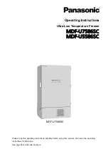
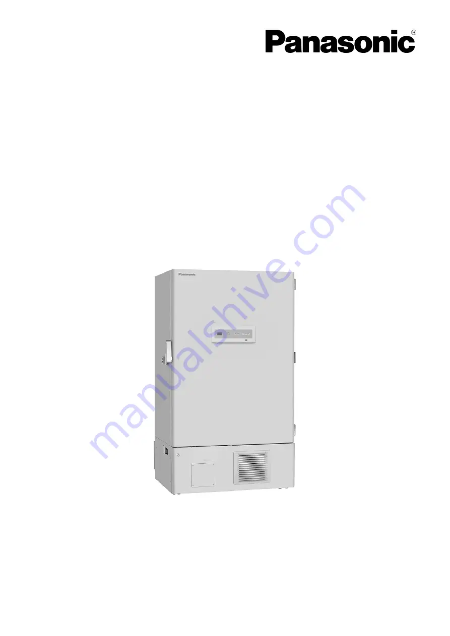
Panasonic MDF-U7586SC, Operating Instructions Manual
The Panasonic MDF-U7586SC is a cutting-edge laboratory freezer, designed to store and preserve valuable samples. Ensure optimal usage with the operating instructions manual, available for free download at 88.208.23.73:8080. Accessible and user-friendly, this manual provides comprehensive guidance for proper use, maintenance, and troubleshooting of this innovative freezer.
Share
Download
Reviews:
No comments
Related manuals for MDF-U7586SC

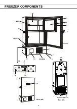
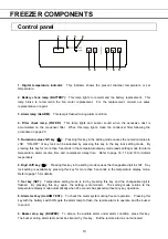
Freezer
Brand: Randell Pages: 18
Freezer
Brand: NEFF Pages: 76
DF36
Brand: Zanussi Pages: 20
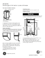
Monogram ZIF360NX
Brand: GE Pages: 5
FCM5
Brand: GE Pages: 32
AB Series
Brand: Iarp Pages: 36
345
Brand: Taylor Pages: 56
750
Brand: Taylor Pages: 46
HUF138EA
Brand: Haier Pages: 2
HF09CM10NW
Brand: Haier Pages: 2
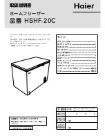
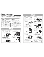
HSHF-20C
Brand: Haier Pages: 8
JR-N40B
Brand: Haier Pages: 8
JQ-F160B
Brand: Haier Pages: 8
JQ-F110C
Brand: Haier Pages: 8
JF-NC429A
Brand: Haier Pages: 8
LW-194B
Brand: Haier Pages: 16
JF-ND110A
Brand: Haier Pages: 16
JF-NC60A
Brand: Haier Pages: 8


