2
Names and Functions of Part
s
Cha
p
ter 1
1.1 About the AX40
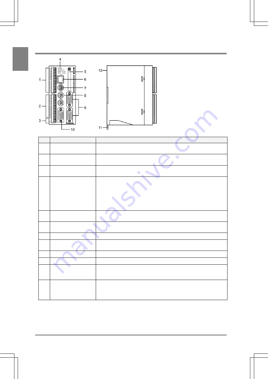
No.
Designation
Description
1
External output terminal
(16 pins)
An external output terminal. The AX40 uses a Phoenix connector (product
#: 1840502).
2
External input terminal
(15 pins)
An external input terminal. COMMON terminal is for (+/-). The AX40 uses a
Phoenix terminal block (product #: 1840528).
3
Power terminal
Acceptable input voltage is 24V DC. The power terminal is located on the
input terminal block.
4
Operating LEDs
Indicate the operating status of the AX40.
• POWER
(green):
The green LED is lit while the AX40 is being energized.
• ERROR
(red):
The red LED is lit when an error is detected.
• READY
(green):
The green LED is lit when various signals including start signal can be input.
5
CF card slot
Supports for a FAT16- formatted and up to 512 MB of compact flash
memory.
6
TOOL port (Ethernet
Port)
Connects to the external device via Ethernet port. Use a cross cable for the
connection.
7
KEYPAD connector
Connects to the operation keypad.
8
COM1 port (RS232C
port)
Connects to an external device via the port.
9
Camera connectors
Connect up to two cameras: CAMERA 1 and CAMERA 2.
10
MONITOR
Connects to the VGA monitor
11
DIN rail attachment
lever (for hooking with
one-touch operation)
Offers quick and easy mounting of the device onto the DIN rail.
12
Backup battery
This is a battery for retaining information about calendar in the AX40. If the
backup battery runs out, the screen monitor displays “Battery used up!””. In
such a case, replace with a new battery. Product number: AFPG804
(Effective life: About 10 years at 25°C)
Caution
Connect only the specified products to the AX40.
Summary of Contents for Micro-Imagechecker AX40
Page 9: ...1 Names and Functions of Parts Chapter 1 Chapter 1 Names and Functions of Parts ...
Page 15: ...7 Installation and Wiring Chapter 2 Chapter 2 Installation and Wiring ...
Page 25: ...17 Input and Output Interface Ports Chapter 3 Chapter 3 Input and Output Interface Ports ...
Page 42: ......
Page 70: ......
Page 94: ...86 Setting Checkers Chapter 6 6 7 Gray Edge 6 7 1 Menu Options ...
Page 108: ...100 Setting Checkers Chapter 6 6 9 Smart Matching 6 9 1 Menu Options ...
Page 184: ......
Page 185: ...177 TOOL Chapter 8 Chapter 8 TOOL ...
Page 192: ......
Page 193: ...185 Environment Settings Chapter 9 Chapter 9 Environment Settings ...
Page 215: ...207 Chapter 10 Parallel Communication Chapter 10 Parallel Communication ...
Page 225: ...217 Chapter 11 RS232C Communication Chapter 11 RS232C Communication ...
Page 255: ...247 Chapter 12 Ethernet Communication Chapter 12 Ethernet Communication ...
Page 261: ...253 Chapter 13 Using a CF Card Chapter 13 Using a CF Card ...
Page 279: ...271 Chapter 15 Troubleshooting Chapter 15 Troubleshooting ...
Page 292: ...284 Specifications and Product Numbers Chapter 16 Camera Cable Keypad ...
Page 294: ...286 Specifications and Product Numbers Chapter 16 ANM88161 ANM88251 ANB842NL Unit mm ...


