No.SX-DSV01676
- 31 -
R2
Motor Company, Matsushita Electric Industrial Co., Ltd.
Control output
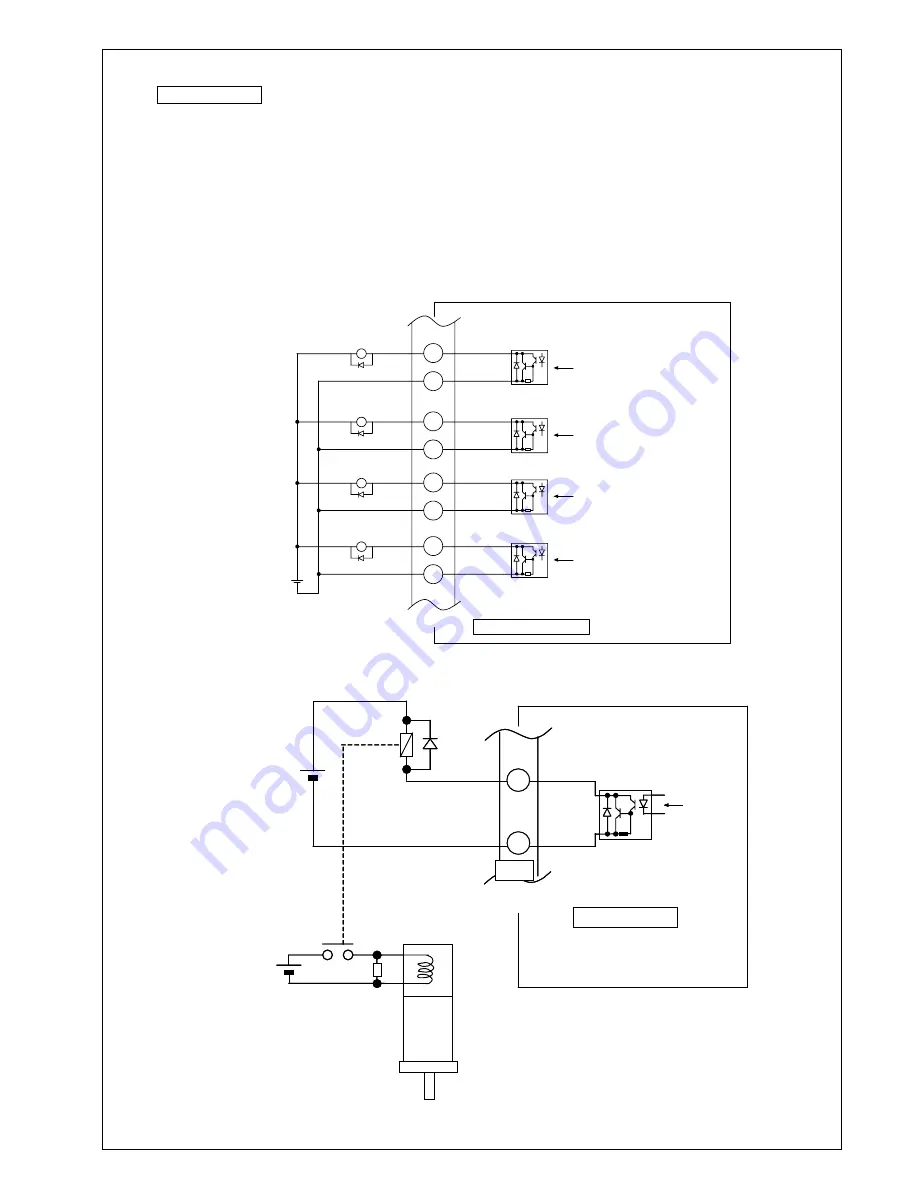
1
)
Pay attention to the polarity of the control power supply. The servo drive will be damaged
with a reverse polarity connection to the fig. below.
2
)
When the relays are directly driven by each output signal, install a diode in parallel with a relay in the
same direction as the fig. below without fail. The servo drive will be damaged if no diode,
or installed in reverse direction.
3
)
Pay attention not to subject to the noise disturbance when each output signal is received by a logic
circuit such as a gate IC.
4
)
Limit the current to each output to 50mA or less.
DC 12 to 24V
X5
Servo drive side
16
15
ALM-
ALM+
ALM
MAX 50mA
35
36
BRK-OFF-
BRK-OFF+
BRK-OFF
MAX 50mA
30
29
EX-OUT1-
EX-OUT1+
EX-OUT1
MAX 50mA
32
31
EX-OUT2-
EX-OUT2+
EX-OUT2
MAX 50mA
When release, transistor ON.
When alarm, transistor OFF.
5
)
Connect the circuit externally as the following figure when operating the brake with BRK-OFF output.
Note: If necessary, connect a fuse in series with the surge absorber.
BRK-OFF+
BRK-OFF-
DC12 to 24V
CN X5
Max 50mA
DC24V
Surge
absorber
Relay
Brake
Motor
Diode
BRK-OFF
35
36
サーボアンプ側
BRK-OFF+
BRK-OFF-
DC12 to 24V
CN X5
Max 50mA
DC24V
Surge
absorber
Relay
Brake
Motor
Diode
BRK-OFF
35
36
サーボアンプ側
Servo drive side
X5
Phone: 800.894.0412 - Fax: 888.723.4773 - Web: www.clrwtr.com - Email: info@clrwtr.com


