No. SX-DSV02829 -
123-
Class No.
Attri
bute
*1)
Title
Range
Unit
Function
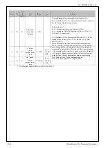
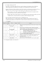
6
69
B
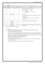
2nd anti-resonance
damping ratio
0-1000
-
Sets the 2nd anti-resonance damping ratio of the load in mode of model
type damping filter enabled.
Damping ratio is set by the setting value x 0.001.
When the set value of 1000, damping 1 (no peak).
Decreasing the setting value, the damping ratio is reduced. (Resonance
peak is large)
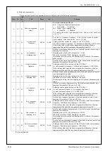
6
70
B
2nd response
frequency
0-3000
0.1Hz
Sets the 2nd response damping ratio of the load in mode of model type
damping filter enabled.The unit is [0.1Hz].
Setting possible within the scope of the 10.0 [Hz]
≦
2nd anti-resonance
frequency
≦
2nd response frequency
≦
2nd anti-resonance frequency x 4
≦
300.0 [Hz].
If the setting value is not the above magnitude relationship, vibration
suppression filter and filter resonance characteristic is invalid.
*1) For the parameter attributes, refer to Section 9-1.
5) How to use
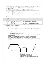
(1) Using torque velocity mode of the frequency response measurement in PANATERM, measure
resonance frequency and anti-resonance frequency in advance, and set each parameter with these
frequencies.
* When analyzing frequency in “Torque velocity (vertical) mode”, set bit6 “Switching of position
loop frequency characteristic” of Pr6.47 “Function expansion setup 2” to “0: Existing function
(Torque velocity vertical axis mode).”
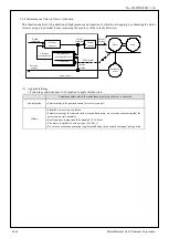
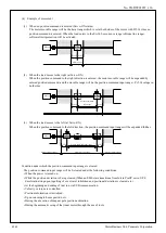
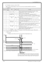
e.g. The screenshot below shows measurement results of a belt device. With small resonances
ignored, the following are the resonance frequency of the gain’s peak and anti-resonance
frequency of the gain’s valley.
1) 1st anti-resonance frequency
=
44[Hz],
2) 1st resonance frequency
=
130[Hz]
3) 2nd anti-resonance frequency
=
180[Hz]
、
4) 2nd resonance frequency
=
285[Hz]
、
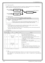
(2) Set bit0 and bit5 of Pr6.47 (Function expansion setup 2) to “1” and reset the power to enable the model
type damping control.
(3) For resonance damping ratio and anti-resonance damping ratio, set their default to 50 (0.050) or so.
(4) For response frequency, start with the same value as the one of anti-resonance frequency.
(5) Actually start the motor and fine-tune the parameters in the following order to decrease vibration
components such as command position deviation.
(1) anti-resonance frequency
(2) anti-resonance damping ratio
(3) resonance frequency
(4) anti-resonance damping ratio
(6) When the combination of the settings where the least vibration is generated is found, increase the response
frequency setting. The response frequency will increase up to a value of 1 to 4 times of the anti-resonance
frequency. The higher the frequency, the smaller the delay in damping control becomes. However, as
damping effects gradually decrease, try to find balanced settings.
R1.00
Motor Business Unit, Panasonic Corporation


