No. SX-DSV02829 -
149-
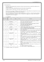
Error No.
Protective
function
Causes
Measures
Main
Sub
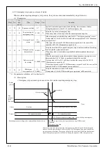
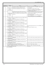
33
8
Latch input
allocation error
protection
Error has occurred during function assignment of latch
correction pins (SI5, SI6, and SI7).
• EXT1 must be allocated to SI5 and EXT2 to SI6: but
these are assigned to other pins.
• HOME is allocated to SI6 or SI7; POT is allocated to
SI5 or SI7; NOT is allocated to SI5 or SI6.
• Function is allocated to b-contact.
• Function not allocated to one or more control modes.
Allocate correct function to each connector pin.
34
0
Software limit
protection
When a position command within the specified input
range is given, the motor operates outside its working
range specified in Pr 5.14 (Motor working range setup).
1) Gain is not appropriate.
2) Pr 5.14 setup value is low.
1) Check the gain (balance between position loop gain and
velocity loop gain) and inertia ratio.
2) Increase the setup value of Pr 5.14. Or, Set Pr 5.14 to 0 to
disable the protective function.
36
0
EEPROM
parameter error
protection
Data in parameter storage area has been damaged when
reading the data from EEPROM at power-on.
• Set up all parameters again.
• If the error persists, replace the driver (it may be a failure.)
Return the product to the dealer or manufacturer.
1
2
37
0
EEPROM check
code error
protection
Data for writing confirmation to EEPROM has been
damaged when reading the data from EEPROM at
power-on.
Replace the driver. (it may be a failure). Return the product to
a dealer or manufacturer.
1
2
38
0
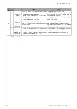
Over-travel inhibit
input protection 1
With Pr 5.04, over-travel inhibit input setup = 0, both
positive and negative over-travel inhibit inputs
(POT/NOT) have been ON.
With Pr 5.04 = 2, positive or negative over-travel inhibit
input has turned ON.
With Pr 5.04 = 0, and either of the positive and negative
over-travel inhibit input has turned ON during the
execution of magnet pole position estimation.
With Pr 5.04 = 0, and either of the positive and negative
over-travel inhibit input has turned ON during automatic
linear motor setup,
Check that there are not any errors in switches, wires or power
supply which are connected to positive direction/ negative
direction over-travel inhibit input. Check that the rising time
of the control power supply (12 to 24 VDC) is not slow.
1
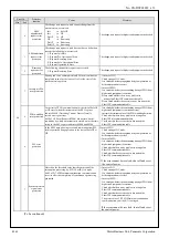
Over-travel inhibit
input protection 2
An operation command (e.g. test run, FFT) has been
received through USB communication (PANATERM)
while EtherCAT communication is OFF with Pr 5.04
"over-travel inhibition input setting" = 0 or 1, and either
POT or NOT is ON.
Or, POT or NOT is turned ON while the system is
operating according to the command given through USB
communication.
Check that there are not any errors in switches, wires or power
supply which are connected to positive direction/ negative
direction over-travel inhibit input. Check that the rising time
of the control power supply (12 to 24 VDC) is not slow.
2
Over-travel inhibit
input protection 3
With POT allocated to SI6 or NOT to SI7, Pr 5.04
over-travel inhibit input setup is set to a value other than
1.
• When POT is allocated to SI6 or NOT allocated to SI7,
make sure that Pr 5.04 over-travel inhibit input setup is set
to 1.
(To be continued)
R1.00
Motor Business Unit, Panasonic Corporation


