No. SX-DSV02829 -
10-
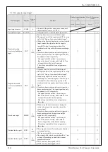
Title of signal
Symbol
Connector
pin No.
*2)
Contents
Related control mode
*1)
EtherCAT communi-
cations
Position
Velocity
Torque
command
monitor
*3)
General purpose
monitor input 1
SI-MON
1
*
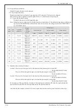
• Used as the general purpose monitor input.
• This input does not affect the operation, and can
be used for monitoring through 60FDh(Digital
inputs).
-
○
General purpose
monitor input 2
SI-MON
2
*
-
○
General purpose
monitor input 3
SI-MON
3
12
(SI7)
-
○
General purpose
monitor input 4
SI-MON
4
13
(SI8)
-
○
General purpose
monitor input 5
SI-MON
5
5
(SI1)
-
○
External alarm clear
input
A-CLR
*
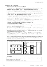
• Dis arm inputs the alarm.
• There are alarms that cannot be dis armed by this
input.
-
-
*1) The triangle in the table under [Control mode] indicates that the turning ON/OFF of the input signal does not affect
system operation.
*2) Except for I-COM, input signal pin assignment can be changed. The pins in “Connector pin No.” column in the table
denote factory default settings. The signal with a pin that is marked with “*” is not assigned by default. For more
information, refer to “2-4-1 Input signal allocation”.
*3) It is possible to monitor the condition of the signals
where “○” is attached to the EtherCAT communication monitor on
the table with 60FDh (Digital inputs).
R1.00
Motor Business Unit, Panasonic Corporation

