-
19
-
-
18
-
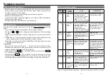
How to use Digital key pad (option)
Function of Digital key pad
• Monitoring of rotation speed (actual speed) and load factor, etc.
• Display detail of trip, and trip history. Trip reset by pressing and .
• Parameter setting, initialization, and copying function.
• Teaching function (Target point (positioning point) can be set by actually starting the
motor.)
■
When using Digital key pad, the Digital key pad connection cable (DV0P383**/
option) is required.
Using the Digital key pad
• When power is turned on, rotation speed (actual speed) r/min is displayed in monitor
mode (changeable by Pr7A).
• Displayed value is an index. Do not use the Digital key pad for a measuring instrument.
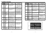
5-digit
LED
■
In monitor mode
Displays rotation speed (actual
speed), commanded speed, present
position, trip history, and the like.
■
In parameter editing
Displays a parameter setting value.
■
In teaching
Displays present position of motor.
•
is displayed for indicating
a negative value.
2-digit
LED
■
In monitor mode
The left value (position of 10) indicates an operation command signal status.
( : Stand still, : Commanding)
The right value (position of 1) indicates a rotation direction and operation status.
( : Operating in dir*, : Operating in direction –*, : Stand still, : Motor
is free)
■
In parameter editing
Displays the number of parameter.
■
In teaching
Displays the point number of parameter.
• Rotation direction is changed by Pr23.
Dir ( ): CCW rotation when viewed from motor output shaft (default).
Switch
When
switch is pressed, the setting change warning
(CAU) is displayed, and the motor is stopped and tripped.
Switch
■
In monitor mode
When this switch is pressed for about 4 seconds, system shifts to
teaching mode.
■
In teaching
When homing is not completed, homing operation is executed by
pressing this switch for about 4 seconds in teaching mode.
Switch
■
In monitor mode
Trip reset can be executed by pressing and at the same
time.
■
In parameter editing
This switch allows selection of parameter, and setting and changing
of details.
Parameter changes continuously while this switch is held down.
■
In teaching
When homing is completed, teaching operation (motor drive) is
enabled by the switch and .
Switch
■
In monitor mode
Switch for changing monitor mode. Whenever this switch is pressed,
the mode changes in this sequence:
Rotation speed (actual speed)
→
Internal DC voltage (voltage of
smoothing capacitor in power supply)
→
Load factor
→
Torque
→
Commanded speed
→
Present position (lower 5 digits)
→
Present position (shaft rotation number)
→
Rotation speed (actual
speed)
→
....
■
In parameter editing, and in teaching
System shifts to monitor mode. (Setting is not saved in EEPROM.)
Switch
■
In monitor mode
System shifts to parameter number mode.
■
In parameter editing
This switch is for changing parameter number mode and parameter
setting mode, and for saving parameter setting in EEPROM.
■
In teaching
This switch is for changing point number mode and teaching mode,
and for saving setting in EEPROM (nonvolatile memory built in the
amplifier).


