-
27
-
-
26
-
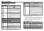
Test run
Description of
operation
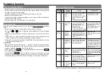
1.Turn on power
2.Set the action
Pr4E
Setting of
(
teaching speed
)
3.Return to
monitor mode.
Operation panel
Switch
LED display
Press
Press and choose parameter 4E
(teaching speed).
(Initial setting: 50)
Press
Press and change the teaching speed to 300.
Press
Press
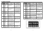
4.Teaching
operation
5.Exit
Press
Press for 4 seconds
When is pressed in this condition, the
motor rotates in + direction* and 5-digit
LED indicates position coordinates.
When is pressed after the motor has
stopped, the motor rotates in one direction.
When is released, the motor stops.
(LED display "5000" is an example, which
shows the present position of the motor.)
When exiting the mode without setting
data, press switch to return to
monitor mode.
When is released, the motor stops.
(LED display ". . 3.5.5." indicates that
the present position is –355.)
Flashing
Flashing
Flashing
Flashing
Flashing
Flashing
Flashing
Flashing
All light up.
All light up.
All light up.
All light up.
All light up.
All light up.
Flashing
Flashing
Flashing
Description of
operation
Operation panel
Switch
LED display
Inspection before Test run
1) Make sure that all wiring is correct.
2) Make sure that input power supply conforms to rating.
Test run
Procedure for test run using the Digital key pad is as follows:
Shown here is the case of running at 300r/min in direction CW or CCW by use of teaching
function.
First execute the following work for safe operation.
[1] Ensure that the motor alone can be operated.
[2] Turn on power and follow the steps below for test run.
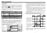
Checkpoint in Test run
[1] Check whether the motor rotates smoothly. Check for abnormal noise and vibration.
[2] Check whether the motor is accelerated and decelerated smoothly.
[3] Make sure that the direction of motor rotation is correct.
* Rotation dir represents CCW on the motor shaft in default setting. (Can be
changed by Pr23 coordinate system setting.)
Rotation direction of gear head output shaft may sometimes be reversed due to re-
duction gear ratio when gear head is installed.
(See the table of permissible shaft torque on P.29. Rotation direction is described.)


