-
E15
-
-
E14
-
English
Conformance to EC directive and UL standard/ Specifications
EC Directives
The EC directives apply to all such electronic products as those having specific functions
and directly sold to general consumers in EU countries. These products are required to
meet the EU unified standards and to be furnished with CE marking.
Our brushless motor and amplifier meet the EC Directives for Low Voltage Equipment so
that the machine or equipment comprising our brushless motor and amplifier can meet
relevant EC Directives.
EMC Directives
Our brushless motor can meet EMC Directives and related standards. However, to meet
these requirements, the systems must be limited with respect to configuration and other
aspects, e.g. the installation and some special wiring conditions must be met. This means
that in some cases machines and equipment comprising our brushless systems may
not satisfy the requirements for wiring and grounding conditions specified by the EMC
Directives. Therefore, conformance to the EMC Directives (especially the requirements for
emission noise and noise terminal voltage) should be examined based on the final products
that include our system.
Applicable standard
Applicable standard
UL
UL1004
Standard for electric motor
CSA
(c-UL)
C22.2 No.100
Standard for electric motor
CE
EN60034-1
Standard for rotary electric machine (low voltage directive)
EN60034-5
Standard for rotary electric machine (low voltage directive)
CCC
GB12350
Safety standard for low-power electric motor
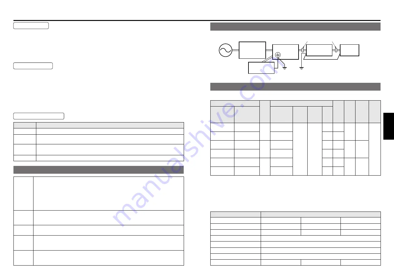
Configuration of peripheral equipment
Power
supply
・
100 V system: Single phase 100 V to 120 V ± 10%, 50/60 Hz
200 V system: Single phase 200 V to 240 V ± 10%, 50/60 Hz
・
Use the equipment under the environment of overvoltage category II specified by
IEC60664-1.
In order to obtain overvoltage category III, insert a transformer conforming to EN
standard or IEC standard to the input of brushless amplifier.
・
Use an electric wire size suitable to EN60204-1.
Circuit
breaker
Fuse
Be sure to connect a specified no-fuse breaker certified by IEC standard or UL, or
a fuse certified by UL between power supply and noise filter. Meeting this condition
allows conformance with UL508C (file No. E164620) and UL1004 (file No. E166557).
Noise
filter
When installing one noise filter at the power supply for more than one brushless motor
used, contact the manufacturer of noise filter.
Surge
absorber
Install a surge absorber on the primary side of noise filter. However, in performing
the voltage resistance test of machine and equipment, be sure to remove the surge
absorber; otherwise, the surge absorber may be ruptured.
Grounding
Be sure to connect the grounding Terminal of brushless amplifier and protective
grounding wire (PE) of system for preventing electric shock. Do not tighten the
grounding wires together but connect them individually.
Conformance to EC directive and UL standard
Wiring of peripheral equipment
Specifications
• General specification
Model name
Rated
output
(W)
Power input
Motor
Rated
Current
(A)
Rated
torque
(N
・
m)
Starting
torque
(N
・
m)
Rated
rotation
speed
(r/min)
Brushless
*
motor
Brushless
*
amplifier
Voltage
(V)
Tolerance
(%)
Frequency
(Hz)
Rated
input
current
(A)
MBMU5AZA
*
MBEG5A1BC
*
50
Single phase
100 to 120
±10
50/60
1.5
0.53
0.16
0.24
3000
MBMU5AZA
*
MBEG5A5BC
*
Single/3-phase
200 to 240
0.7
0.53
MBMU9A1A
*
MBEG9A1BC
*
90
Single phase
100 to 120
2.2
1.0
0.29
0.43
MBMU9A2A
*
MBEG9A5BC
*
Single/3-phase
200 to 240
1.1
0.5
MBMU1E1A
*
MBEG1E1BC
*
130
Single phase
100 to 120
2.8
1.3
0.41
0.62
MBMU1E2A
*
MBEG1E5BC
*
Single/3-phase
200 to 240
1.5
0.72
*
The “
*
” in the motor designation is replaced with the symbol indicating the shaft specification.
*
The “
*
” in the amplifier designation is replaced with the character V indicating GV series or
P indicating GP series.
• Never use a GP series amplifier in combination with a GV series motor.
A wrong combination will cause malfunction.
• Common specification
Item
Specifications
Brushless motor
MBMU5AZA
*
MBMU9A
*
A
*
MBMU1E
*
A
*
Brushless amplifier
MBEG5A
*
BC
*
MBEG9A
*
BC
*
MBEG1E
*
BC
*
Rated output (W)
50
90
130
Rated speed
3000 r/min
Speed control range
30 to 4000 r/min (Speed ratio 1:133)
Motor heat resistance class
130(B) (UL certified 105 (A))
Time rating
Continuous
Motor mass (kg)
(
0.7
)
(
1.0
)
(
1.2
)
Molded Case
Circuit Breaker
(MCCB)
or Fuse
Brushless
amplifier
Brushless
motor
Surge
absorber
Noise filter
Protection ground
(PE)
ground
Power
supply
Ferrite core (Noise filter for signal line)
option DV0P1460 (*Qty.
:
4 ) (part No.: ZCAT3035-1330/TDK Corp.)
* The ferrite core should insert one
or more pieces in an electric wire,
respectively.


