background image

8 TROUBLESHOOTING GUIDE

DANGER: HIGH VOLTAGES

1. Ensure proper grounding before troubleshooting.
2. Be careful of high voltage circuit.
3. Discharge high voltage capacitor.
4. When checking the continuity of the switches or the high voltage transformer,disconnect one lead wire from these parts and then check
continuity with the AC plug removed. To do otherwise may result in a false reading or damage to your meter.
When disconnecting a plastic connector from a terminal, you must hold the plastic connector instead of the lead wire and then disconnect it,
otherwise lead wire may be damaged or the connector cannot be removed.

Before troubleshooting, operate the microwave oven following the correct operating procedures in the instruction manual in order
to find the exact cause of any trouble, since operator error may be mistaken for the oven’s malfunction.

14

NE-1022F

Summary of Contents for NE-1022F

Page 1: ... Panasonic Appliances Microwave Oven Shanghai Co Ltd 2012 NE 1022F APH USA Microwave Oven ORDER NO PAPMOSH1201014CE E10 ...

Page 2: ...2 NE 1022F ...

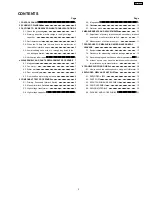
Page 3: ... Switch 9 5 3 High voltage transformer 9 5 4 High voltage capacitor 9 5 5 Magnetron 9 5 6 Diode 10 5 7 Protector diode 10 6 MEASUREMENTS AND ADJUSTMENTS 11 6 1 Adjustment of primary interlock switch secondary interlock switch and monitor interlock switch 11 6 2 Measurement of microwave output 11 7 PROCEDURE FOR MEASURING MICROWAVE ENERGY LEAKAGE 12 7 1 Equipment 12 7 2 Procedure for measuring radi...

Page 4: ...1 CONTROL PANEL 4 NE 1022F ...

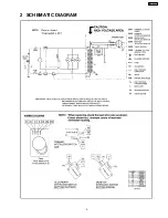
Page 5: ...2 SCHEMATIC DIAGRAM 5 NE 1022F ...

Page 6: ... the malfunction of the monitor interlock switch WARNING When the 10 Amp fuse is blown due to malfunction of the short switch replace all of the components Primary interlock switch Secondary interlock switch Monitor interlock switch 1 This is mandatory Refer to Measurements and Adjustments for the location of these switches 2 When replacing the fuse confirm that it has the appropriate rating for t...

Page 7: ... FA terminal 4 2 Fan motor 1 Disconnect 2 lead wires from fan motor terminals 2 Disconnect 2 lead wires from fuse holder terminals 3 Disconnect 4 high voltage lead wires from high voltage capacitor terminals 4 Remove 5 screws holding fan motor and orifice assy detach the orifice assy with fan motor from oven assy 5 Remove fan blade from the fan motor shaft by pulling it straight Out 6 Separate the...

Page 8: ...oor is misaligned apply pressure until alignment is achieved NOTE Adjust so that the upper portion of the door will touch firmly to the oven cavity front plate without pushing the door If the door assembly is not mounted properly microwave power may leak from the clearance between the door and oven Be sure the gap between door E and cavity front plate will be 0 3 0 8mm NOTE Always perform the micr...

Page 9: ...er Normal continuity readings should be as follows 5 3 High voltage transformer 1 Remove connectors from the transformer terminals and check continuity 2 Normal cold resistance readings should be as follows Secondary winding Approx 60 Ω 120 Ω Filament winding Approx 0 Ω Primary winding Approx 0 Ω 2 Ω 5 4 High voltage capacitor 1 Check continuity of capacitor with meter on highest OHM scale 2 A nor...

Page 10: ...esistance may be read in both directions A normal diode s resistance will be infinite in one direction and several hundred kΩ in the other direction 5 7 Protector diode 1 Isolate the protector diode assembly from the circuit by disconnecting its leads 2 With the ohmmeter set on the highest resistance scale measure the resistance across the protector diode terminals Reverse the meter leads and agai...

Page 11: ...e monitor circuit and all interlock switches again by following the component test procedures 6 2 Measurement of microwave output The output power of the magnetron can be determined by performing IEC standard test procedures However due to the complexity of IEC test procedures it is recommended to test the magnetron using the simple method outlined below Necessary Equipment 1 liter beaker Glass th...

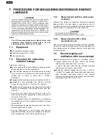
Page 12: ...age always use the 2 inch 5cm spacer supplied with the probe 4 Tap the Start button or set the timer and with the magnetron oscillating measure the leakage by holding the probe perpendicular to the surface being measured 7 2 1 Measurement with the outer panel removed Whenever you replace the magnetron measure for radiation leakage before the outer panel is installed and after all necessary compone...

Page 13: ...7 4 At least once a year have the radiation monitor checked for calibration by its manufacturer 13 NE 1022F ...

Page 14: ... removed To do otherwise may result in a false reading or damage to your meter When disconnecting a plastic connector from a terminal you must hold the plastic connector instead of the lead wire and then disconnect it otherwise lead wire may be damaged or the connector cannot be removed Before troubleshooting operate the microwave oven following the correct operating procedures in the instruction ...

Page 15: ...8 1 How to check the semiconductors using an OHM meter 15 NE 1022F ...

Page 16: ...9 EXPLODED VIEW AND PARTS LIST 9 1 EXPLODED VIEW 16 NE 1022F ...

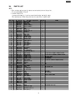
Page 17: ...F40253700BP AIR GUIDE A 1 22 F41445540AP ORIFICE 1 23 F621B6P10AP H V TRANSFORMER 1 25 F612E5Y30AP INCANDESCENT LAMP U 1 26 J6142 1450 MICRO SWITCH 1 V 16G 3C26 M PRIMARY INTERLOCK SWITCH 27 J6142 1450 MICRO SWITCH 1 V 16G 3C26 M SECONDARY INTERLOCK SWITCH 28 F61448K00AP ANTENNA MOTOR 1 29 F61456N00AP THERMAL CUTOUT 1 FOR OVEN CAVITY 30 F61458K10AP THERMAL CUTOUT 1 FOR MAGNETRON 32 ANE6161 3X0 MIC...

Page 18: ...me Description Pcs Set Remarks E1 F00078K70AP NAME PLATE 1 E2 F60018K20AP TIMER SWITCH 1 E5 F80206P00AP TIMER KNOB 1 E6 F80346P00AP ESCUTCHEON BASE 1 E10 F80356P00AP ESCUT FACIA 1 E12 XTWEFNE3 8Q SCREW 1 E14 F800L8K20SAP ESCUTCHEON BASE BU 1 18 NE 1022F ...

Page 19: ...C 1 D7 F302K3700BP DOOR E U 1 D8 F31454J50XN DOOR SCREEN A 1 D9 F30016P00AP DOOR A 1 D10 F30026P00AP DOOR B U 1 D11 F31466P00AP DOOR SCREEN B 1 D12 F32863700AP HANDLE BRACKET 1 D13 F30706P00AP HANDLE PIECE A 1 D14 F31466P00AP HANDLE PIECE B 1 D15 F90096P00AP EARTH PLATE 1 D16 XTN4 16Q SCREW 2 D17 XTN4 8C SCREW 4 D18 XTCAFL4 12AFS SCREW 2 D19 F301F6P10AP HANDLE U 2 D20 F302A8K10SAP DOOR A U 1 D25 F...

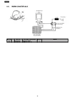
Page 20: ...9 5 WIRING MATERIALS Ref No Part No Part Name Description Pcs Set Remarks W1 F030A8K20AP LEAD WIRE HARNESS 1 61 F606V8K00CP PROTECTOR DIODE U 1 20 NE 1022F ...

Page 21: ...TRUCTION 1 P2 F01028K70SAP PACKING CASE PAPER 1 P3 F01048K00AP UPPER FILLER 1 P4 F01058K00AP LOWER FILLER 1 P5 F01068K00AP P E BAG 1 P6 F01074W00AP DOOR SHEET 1 P8 F01924T00AP SHEET 1 P9 F01088K00AP TRAY PACKING 1 P10 F04243130AP SECURITY BOLT INSTALLATION INSTRUCTION 1 21 NE 1022F 01 12 S 8K7 Printed in China ...

Reviews: