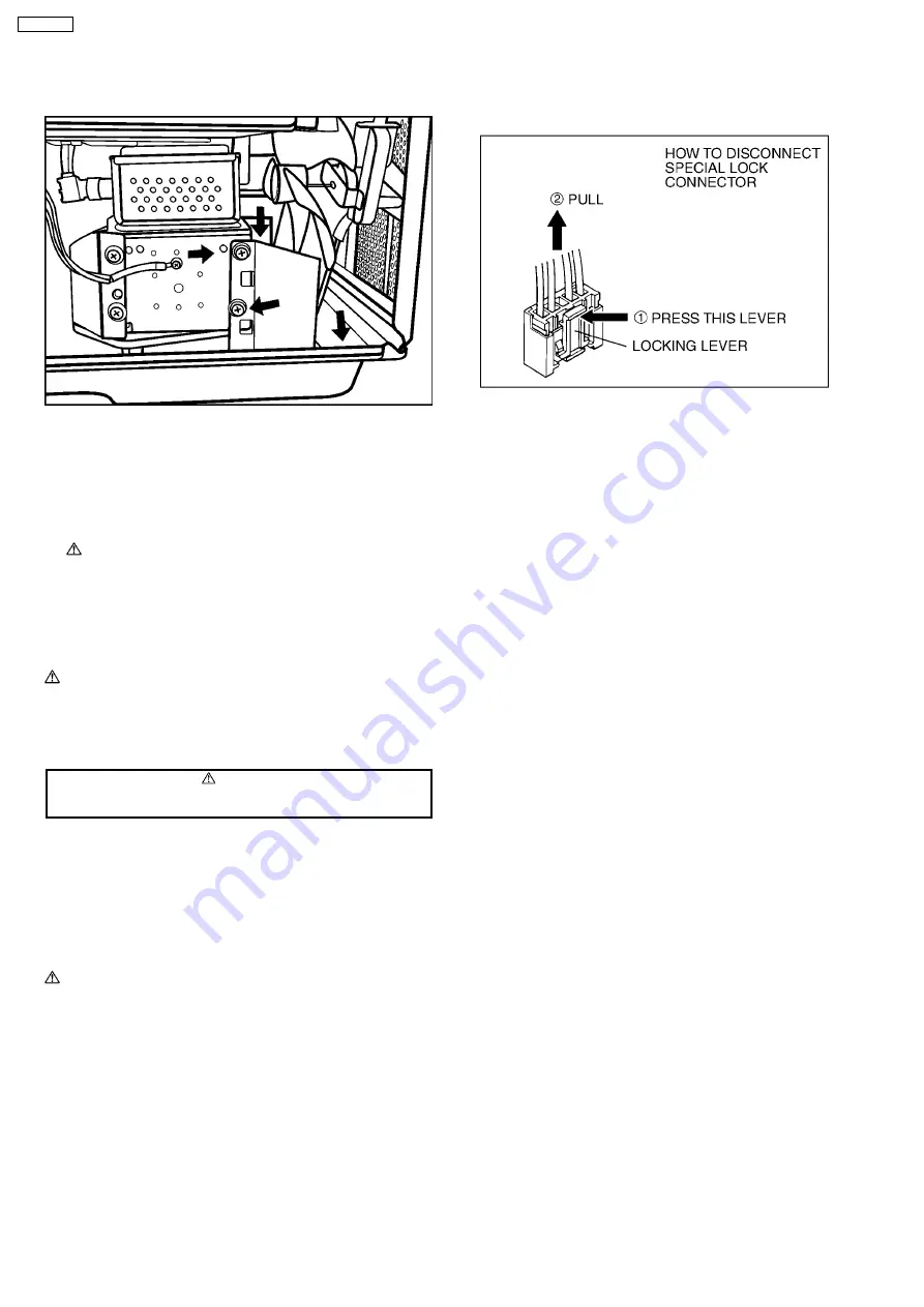
9. Remove 4 screws holding air guide B on magnetron & on
base plate respectively, then remove air guide B.
10. Disconnect 2 lead wires from fan motor terminals.
11. Disconnect lead wires from noise filter (U) terminals.
12. Release locking tabs of inverter reinforcement/grounding
bracket A hanging on both sides of oven cavity, then
withdraw the inverter reinforcement/grounding bracket A
outside slightly.
NOTE:
Pay attention to the sharp edges of inverter
reinforcement/grounding bracket A.
13. Hold the inverter reinforcement/grounding bracket A, then
remove 4 screws holding magnetron.
NOTE:
After replacement of the magnetron, tighten mounting
screws properly in an x pattern, making sure there is no
gap between the waveguide and the magnetron to
prevent microwave leakage.
CAUTION
When replacing the magnetron, be sure the antenna gasket is in
place.
6.2. Digital programmer circuit
(D.P.C) AU, (D.P.C.) HU, key
board membrane and power
relay
CAUTION:
Be sure to ground any static electric charge built up in
your body before handling the DPC.
1. Remove water tank from escutcheon base.
2. Keep pressing [Steam Defrost] pad for more than 2
seconds to drain the water remaining in the water pipes and
tubes into oven cavity.
3. Pull out tube A connecting to pump from copper pipe.
4. Disconnect wiring connectors CN3, CN4, CN8 and all
connectors connecting to power relays from D.P.C. board
HU (relay board).
5. Disconnect wiring connector CN2 from D.P.C. board DU
(power supply board).
6. Remove 1 screw holding escutcheon base on cavity front
plate.
7. Open the door of oven, slide the escutcheon base upward
and out slightly.
8. Disconnect connector CN6 connecting pump-LED (U) from
D.P.C. board HU (relay board).
9. Disconnect 2 flat cables connecting between D.P.C. board
HU and AU from connectors CN5 & CN15 on D.P.C. board
HU by pulling upward slightly.
10. Remove 2 screws holding D.P.C. board HU on escutcheon
base, then remove D.P.C. board HU (relay board).
11. Remove 2 screws holding D.P.C. board AU (display board)
on escutcheon base.
12. Release locking tabs holding D.P.C. board AU (display
board) on escutcheon base then remove 5 screws holding
D.P.C. board AU (rotary dial board) on backstop to remove
D.P.C. board AU.
13. Disconnect 1 flat cable connected from the key board
membrane to connector CN14 on the D.P.C board AU
(display board).
To replace membrane key board
14. Use tools such as kinfe etc. to lift the edge of escutcheon
sheet and peel off escutcheon sheet & key board
membrane completely from escutcheon base.
NOTE:
1. The membrane key board is attached to the
escutcheon base with double faced adhesive tape.
Therefore, applying hot air such as using a hair dryer is
recommended for smoother removal.
14
NN-CS599S
Summary of Contents for NN-CS599S
Page 2: ...2 NN CS599S ...
Page 3: ...3 NN CS599S ...
Page 5: ...1 FEATURE CHART 2 CONTROL PANEL 5 NN CS599S ...
Page 6: ...3 SCHEMATIC DIAGRAM 6 NN CS599S ...
Page 32: ...10 EXPLODED VIEW AND PARTS LIST 10 1 EXPLODED VIEW 32 NN CS599S ...
Page 40: ...11 DIGITAL PROGRAMMER CIRCUIT 11 1 SCHEMATIC DIAGRAM 40 NN CS599S ...
Page 41: ...41 NN CS599S ...


