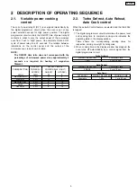
2.1. Variable power cooking
control
The coil of power relay B (RY1) is energized intermittently by
the digital programmer circuit, when the oven is set at any
power selection except for High power position. The digital
programmer circuit controls the ON-OFF time of power relay B
contacts in order to vary the output power of the microwave
oven from ”Low” to “High” power. One complete ON and OFF
cycle of power relay B is 22 seconds. The relation between
indications on the control panel and the output of the
microwave oven is as shown in table.
NOTE:
The ON/OFF time ratio does not correspond with the
percentage of microwave power since approximately 2
seconds are required for heating of magnetron
filament.
OUTPUT
ON-OFF TIME OF
POWERSETTING
POWER(%)
POWER RELAY B (RY1)
APPROX.
ON(SEC)
OFF(SEC)
HIGH
100%
22
0
MEDIUM-HIGH
70%
17
5
MEDIUM
50%
13
9
MEDIUM-LOW
30%
8
14
LOW
15%
5
17
DEFROST
30%
8
14
2.2. Turbo Defrost, Auto Reheat,
Auto Cook control
When those Auto Control feature is selected and the Start Pad
is tapped:
1. The digital programmer circuit determines the power level
and cooking time to complete cooking and indicates the
operating state in the display window.
Table shows the corresponding cooking times for
respective serving or weight by categories.
2. When cooking time in the display window has elapsed, the
oven turns off automatically by a control signal from the
digital programmer circuit.
Turbo Defrost
WEIGHT SELECTED
COOKING TIME
1.0KG
9 min.36 sec.
Auto Reheat
WEIGHT SELECTED
COOKING TIME
2 SERV
3 min.10 sec.
Auto Cook
CATEGORY
WEIGHT SELECTED
COOKING TIME
Vegetable
100g
1 min.50 sec.
2 DESCRIPTION OF OPERATING SEQUENCE
5
NN-G335WF
Summary of Contents for NN-G335WF
Page 2: ...2 NN G335WF ...
Page 4: ...1 SCHEMATIC DIAGRAM 4 NN G335WF ...
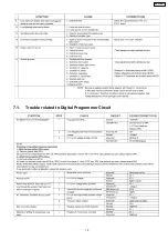
Page 15: ...7 1 Trouble related to Digital Programmer Circuit 15 NN G335WF ...
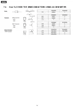
Page 16: ...7 2 How To CHECK THE SEMICONDUCTORS USING AN OHM METER 16 NN G335WF ...
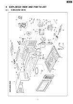
Page 17: ...8 EXPLODED VIEW AND PARTS LIST 8 1 EXPLODED VIEW 17 NN G335WF ...
Page 23: ...9 DIGITAL PROGRAMMER CIRCUIT 9 1 SCHEMATIC DIAGRAM 23 NN G335WF ...
Page 24: ...24 NN G335WF ...


