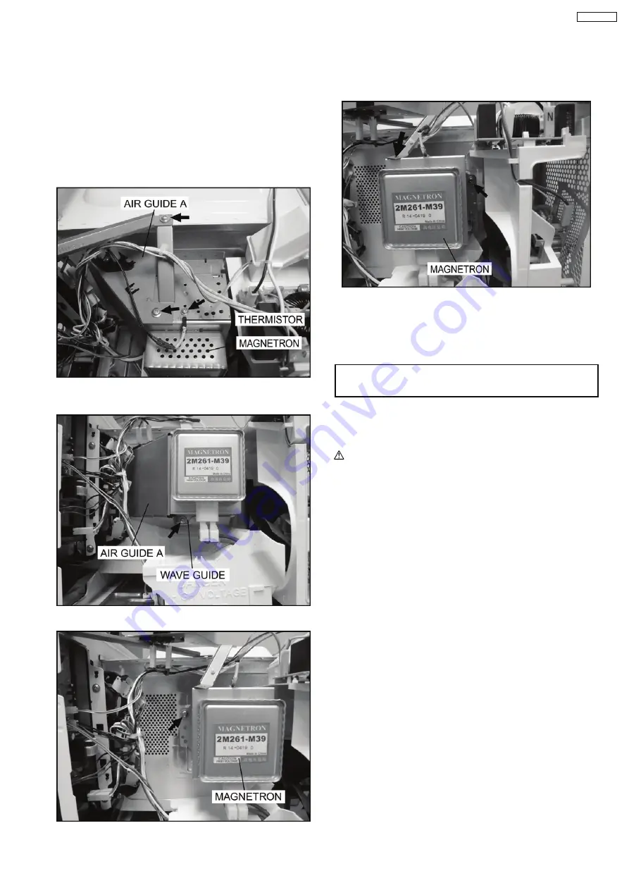
4.1. Magnetron
1. Discharge the high voltage capacitor.
2. Remove 1 screw holding air guide A on the magnetron.
3. Remove 1 screw holding air guide A on cavity top plate.
4. Remove 1 screws holding thermistor on the magnetron.
5. Remove 1 screw holding air guide A on the wave guide,
then remove the air guide A.
6. Remove 2 screws holding the magnetron.
NOTE:
After replacement of the magnetron, tighten mounting
screws properly, making sure there is no gap between
the
waveguide
and
the
magnetron
to
prevent
microwave leakage.
CAUTION
When replacing the magnetron, be sure the antenna gasket is in
place.
4.2. Digital programmer circuit
(D.P.C)
CAUTION:
Be sure to ground any static electric charge built up in
your body before handling the DPC.
1. Disconnect connector CN701 on H.V. Inverter board.
2. Remove 1 screw holding escutcheon base and slide the
escutcheon base upward slightly.
3. Remove all screws holding D.P.C. board on escutcheon
base.
4. Separate D.P.C board from tabs on the escutcheon base
and remove D.P.C board.
To replace membrane key board
5. Use tools such as kinfe etc. to lift the edge of escutcheon
sheet and peel off escutcheon sheet & key board
membrane completely from escutcheon base.
NOTE:
1.
The membrane key board is attached to the
escutcheon base with double faced adhesive tape.
Therefore, applying hot air such as using a hair
dryer is recommended for smoother removal.
2.
When installing the new key board membrane, make
sure that the surface of escutcheon base is clean to
prevent a malfunction or shorted contacts.
4 DISASSEMBLY AND PARTS REPLACEMENT
PROCEDURE
11
NN-GN68KS
Summary of Contents for NN-GN68KS
Page 2: ...2 NN GN68KS...
Page 3: ...3 NN GN68KS...
Page 5: ...1 SCHEMATIC DIAGRAM 5 NN GN68KS...
Page 28: ...8 7 How to check the semiconductors using an OHM meter 28 NN GN68KS...
Page 29: ...9 EXPLODED VIEW AND PARTS LIST 9 1 EXPLODED VIEW 29 NN GN68KS...
Page 36: ...10 DIGITAL PROGRAMMER CIRCUIT 10 1 SCHEMATIC DIAGRAM 36 NN GN68KS...
Page 37: ...37 NN GN68KS...


