4.3. Low voltage transformer
and/or power relays (RY1)
CAUTION:
Be sure to ground any static electric charge built up in
your body before handling the DPC.
1. Replace D.P.C. board.
(A) Using solder wick or a desoldering tool and 30W
soldering iron carefully remove all solder from the terminal
pins of the low voltage transformer and/or power relays.
CAUTION:
Do not use a soldering iron or desoldering tool of
more than 30 watts on D.P.C. contacts.
(B) With all the terminal pins cleaned and separated from
D.P.C. contacts, remove the defective transformer/power
relays, Replace components making sure all terminal pins
are inserted completely resolder all terminal contacts
carefully.
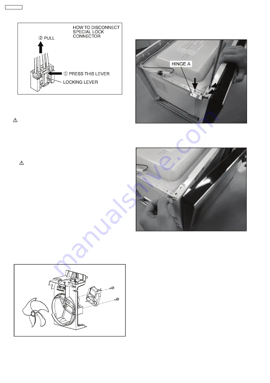
4.4. Fan motor
1. Disconnect 2 lead wires from fan motor terminals.
2. Remove 2 screws at location on oven attaching orifice
assembly.
3. Remove orifice assembly from oven assembly.
4. Remove fan blade from the fan motor shaft by pulling it
straight out.
5. Remove 2 screws holding fan motor to orifice.
4.5. Door assembly
1. Support the door, remove 3 screws holding hinge A.
2. Open the door, remove door(U) and hinge A from cavity.
NOTE:
Support the door before opening.
3. Remove door C from door A (U) & door E by carefully
pulling outward starting from upper right hand corner using
a flat blade screwdriver.
4. Separate door E from tabs on door A (U) and remove door
A (U).
5. Remove door key and door key spring from door E.
12
NN-GN68KS
Summary of Contents for NN-GN68KS
Page 2: ...2 NN GN68KS...
Page 3: ...3 NN GN68KS...
Page 5: ...1 SCHEMATIC DIAGRAM 5 NN GN68KS...
Page 28: ...8 7 How to check the semiconductors using an OHM meter 28 NN GN68KS...
Page 29: ...9 EXPLODED VIEW AND PARTS LIST 9 1 EXPLODED VIEW 29 NN GN68KS...
Page 36: ...10 DIGITAL PROGRAMMER CIRCUIT 10 1 SCHEMATIC DIAGRAM 36 NN GN68KS...
Page 37: ...37 NN GN68KS...


