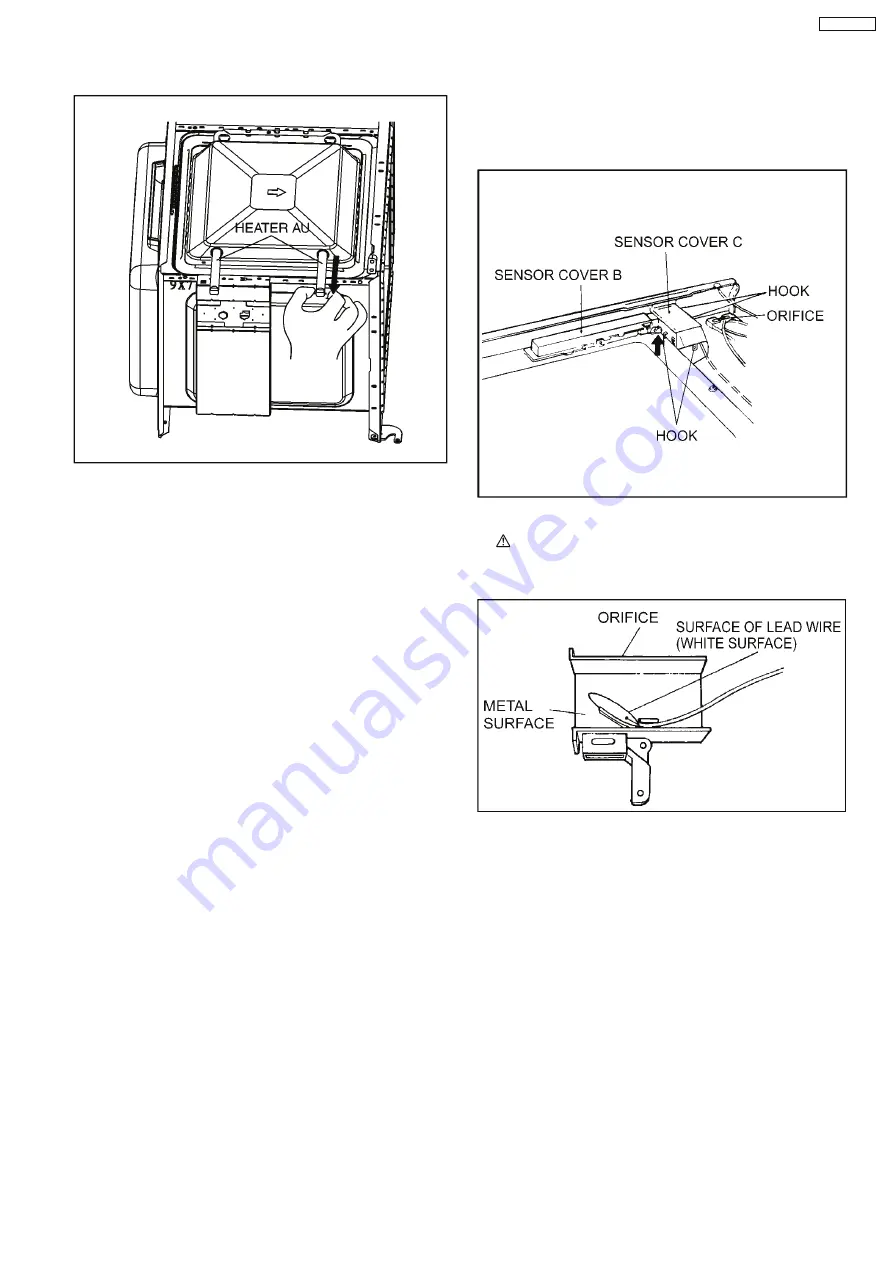
4. Remove the heater by pulling it out from the cavity left side.
4.8. Steam sensor
1. Disconnect connector CN2 from digital programmer circuit
board.
2. Disengage catch hooks on sensor cover C from orifice.
3. Remove steam sensor from orifice.
NOTE:
When installing the steam sensor, make sure that
the direction of steam sensor is as shown in figure.
15
NN-GN68KS
Summary of Contents for NN-GN68KS
Page 2: ...2 NN GN68KS...
Page 3: ...3 NN GN68KS...
Page 5: ...1 SCHEMATIC DIAGRAM 5 NN GN68KS...
Page 28: ...8 7 How to check the semiconductors using an OHM meter 28 NN GN68KS...
Page 29: ...9 EXPLODED VIEW AND PARTS LIST 9 1 EXPLODED VIEW 29 NN GN68KS...
Page 36: ...10 DIGITAL PROGRAMMER CIRCUIT 10 1 SCHEMATIC DIAGRAM 36 NN GN68KS...
Page 37: ...37 NN GN68KS...


