8.4. Trouble related to Digital Programmer Circuit
SYMPTOM
STEP
CHECK
RESULT
CAUSE/CORRECTIONS
No display when oven is first plugged
in
1
Fuse pattern of D.P.C., FUSE1
Normal
→
Step2
Open
Replace D.P.C. or Fuse Pattern
or FUSE
2
Low voltage transforment (L.V.T.)
secondary voltage
Abnormal 0V
L.V.T. (T10)
Normal
→
Step3
3
IC1 pin 13 voltage/IC10 pin voltage
Abnormal
IC10
Normal=5V
IC1, Display
No key input
1
Touch switch continuity
Abnormal
Touch switch
Normal
IC1
No beep sound
1
IC1 pin 49 voltage
Abnormal
IC1
Normal=5V
BZ210, Q210
No microwave oscillation at any power
1
IC1 pin 50 voltages while operation at high
power
Abnormal
IC1
Normal=5V
→
Step2
2
Collector of Q227 voltage
Abnormal
Q227 and/or Q225, Q226
Normal 0.7V
→
Step3
3
Short circuit between collector of Q227
and emitter of Q225
Still not turn on
RL1
RL1 turns on
Q227 and/or Q225, Q226
Dark or unclear display
1
Replace display and check operation
Normal
Display
Abnormal
IC1
Missing or lighting of unnecessary
segment
1
Replace IC1 and check operation
Normal
IC1
Abnormal
Display
H95/H97/H98 appears in window and
oven stops operation.Program High
power for 1 minute and conduct
following test quickly, unless
H95/H97/H98 appears and oven stops
1
Unplug CN702 (2 pin) connector and
measure voltage between terminals
Abnormal=0V
1. Interlock Switch
2. D.P.C. /Power Relay
Normal=120V
→
Step2
2
Unplug CN701 (3 pin) connector and
measure pin1 voltage
Abnormal=0V
D.P.C.
Approx. AC 3V
Magnetron
26
NN-GN68KS
Summary of Contents for NN-GN68KS
Page 2: ...2 NN GN68KS...
Page 3: ...3 NN GN68KS...
Page 5: ...1 SCHEMATIC DIAGRAM 5 NN GN68KS...
Page 28: ...8 7 How to check the semiconductors using an OHM meter 28 NN GN68KS...
Page 29: ...9 EXPLODED VIEW AND PARTS LIST 9 1 EXPLODED VIEW 29 NN GN68KS...
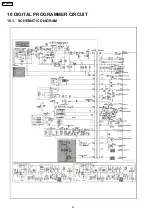
Page 36: ...10 DIGITAL PROGRAMMER CIRCUIT 10 1 SCHEMATIC DIAGRAM 36 NN GN68KS...
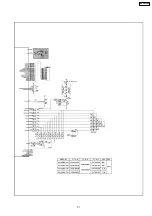
Page 37: ...37 NN GN68KS...


