background image

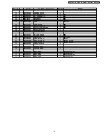
19 PACKING AND ACCESORIES

Ref. No.

Part No.

Part Name & Description

Pcs/Set

Remarks

P1

F00035H00AP

INSTRUCTION MANUAL

1

APH

P1

F00035H00CP

INSTRUCTION MANUAL

1

CPH

P2

F01025H00AP

PACKING CASE PAPER

1

S262SF APH

P2

F01025H10BAP

PACKING CASE PAPER

1

S262BF APH

P2

F01025H10HAP

PACKING CASE PAPER

1

S262WF APH

P2

F01025H20BAP

PACKING CASE PAPER

1

S252BF APH

P2

F01025H20HAP

PACKING CASE PAPER

1

S252WF APH

P2

F01025H00CP

PACKING CASE PAPER

1

S262SF CPH

P2

F01025H10BCP

PACKING CASE PAPER

1

S262BF CPH

P2

F01025H10HCP

PACKING CASE PAPER

1

S262WF CPH

P2

F01025H20BCP

PACKING CASE PAPER

1

S252BF CPH

P2

F01025H20HCP

PACKING CASE PAPER

1

S252WF CPH

P3

F01045H00AP

UPPER FILLER

1

P4

F01055H00AP

LOWER FILLER

1

P5

F01065H00AP

P.E.BAG

1

P6

F01075H00AP

DOOR SHEET

1

P7

A06015H00AP

COOKING TRAY

1

P8

F01175H00AP

TRAY PACKING B

1

S262SF/BF/WF

P9

F01485H00AP

REINFORCE BRACKET

2

P10

F01085H00AP

TRAY PACKING

1

P11

F01925H00AP

SHEET

2

P12

F06025H00AP

OVEN RACK

1

S262SF/BF/WF

P13

F02185H00AP

PROTECTOR PACKING

1

P14

F03135H00AP

INSTALLATION INSTRUCTION

1

P15

F04315H00AP

UPPER-CABINET TEMPLATE

1

APH

P15

F04315H00CP

UPPER-CABINET TEMPLATE

1

CPH

P16

F011F5H00AP

ATTACHMENT

1

33

F400B5H00AP

FILTER (U)

2

32

NN-S262SF / NN-S262BF / NN-S262WF / NN-S252BF / NN-S252WF

Summary of Contents for NNS252BF - MICROWAVE OVEN/OTR

Page 1: ...ushita Microwave Oven Co Ltd All rights reserved Unauthorized copying and distribution is a violation of law NN S262SF NN S262BF NN S262WF NN S252BF NN S252WF APH USA CPH CANADA Microwave Oven ORDER NO SIMMC 0203005C1 E2 ...

Page 2: ...2 NN S262SF NN S262BF NN S262WF NN S252BF NN S252WF ...

Page 3: ...3 NN S262SF NN S262BF NN S262WF NN S252BF NN S252WF ...

Page 4: ...Y AND PARTS REPLACEMENT PROCEDURE 14 10 COMPONENT TEST PROCEDURE 18 11 MEASUREMENTS AND ADJUSTMENTS 20 12 PROCEDURE FOR MEASURING MICROWAVE ENERGY LEAKAGE 21 13 TROUBLESHOOTING GUIDE 23 14 EXPLODED VIEW AND PARTS LIST 27 15 PARTS LIST 28 16 DOOR ASSEMBLY 30 17 WIRING MATERIALS 30 18 ESCUTCHEON BASE ASSEMBLY 31 19 PACKING AND ACCESORIES 32 20 DIGITAL PROGRAMMER CIRCUIT 33 21 DIGITAL PROGRAMMER CIRC...

Page 5: ...erter Turbo Defrost O O Sensor Reheat O Sensor Cooking O Auto Reheat O Inverter Auto Cooking O Quick Min O O Popcorn O O Digital Clock O O Timer O O Child Safety Lock O O Vent Fan O O Cooktop Light O O 2 CONTROL PANEL APH 5 NN S262SF NN S262BF NN S262WF NN S252BF NN S252WF ...

Page 6: ...3 CONTROL PANEL CPH 6 NN S262SF NN S262BF NN S262WF NN S252BF NN S252WF ...

Page 7: ...times and shuts off Time of day or colon if set appears in the display 4 3 Inverter turbo defrost OPERATION SCROLL DISPLAY 1 Press Inverter Turbo Defrost Pad INVERTER TURBO DEFROST SET WEIGHT 2 Set the weight for 1 lb by pressing Number pads 1 Ib 1 0 3 Press Start pad 4 Press Stop Reset Pad twice Oven shuts off Time of day or colon if set appears in the display 4 4 Inverter auto cooking OPERATION ...

Page 8: ...apsed Oven beeps 5 times and shuts off Time of day or colon if set appears in the display 4 7 Power level Press Power Level Power Level Display Window once P10 HIGH P10 twice P9 P9 3 times P8 P8 4 times P7 MED HIGH P7 5 times P6 MEDIUM P6 6 times P5 P5 7 times P4 P4 8 times P3 MEDIUM LOW P3 9 times P2 P2 10 times P1 LOW P1 8 NN S262SF NN S262BF NN S262WF NN S252BF NN S252WF ...

Page 9: ...5 SCHEMATIC DIAGRAM APH 9 NN S262SF NN S262BF NN S262WF NN S252BF NN S252WF ...

Page 10: ...6 SCHEMATIC DIAGRAM CPH 10 NN S262SF NN S262BF NN S262WF NN S252BF NN S252WF ...

Page 11: ... kHz PWM pulse width modulation signal from the microcomputer in the DPC 3 This drives the High voltage transformer to increase up to 2 000V AC and approximately 3V AC by means of transformer 4 Then the half wave doubler voltage rectifier circuit consisting of the H V diodes and Capacitors generates the necessary 4 000V DC needed for the magnetron 5 Output power of the magnetron tube is always mon...

Page 12: ... cause extreme DANGER Be sure to have proper grounding by the grounding plate and screws WARNING OF DISCHARGING HIGH VOLTAGE CAPACITORS Warning about the electric charge in the high voltage capacitors For about 30 seconds after the oven is turned off an electric charge remains in the high voltage capacitors in the inverter power supply circuit board When replacing or checking parts remove the powe...

Page 13: ...all outlet 3 Check for microwave energy leakage Refer to procedure for measuring microwave energy leakage CAUTION MICROWAVE RADIATION DO NOT BECOME EXPOSED TO RADIATION FROM THE MICROWAVE GENERATOR OR OTHER PARTS CONDUCTING MICROWAVE ENERGY IMPORTANT NOTICE NEW H V 1 The following components have potentials above 2000V while the appliance is operated Magnetron High voltage transformer High voltage...

Page 14: ... holding escutcheon base and slide the escutcheon base upward slightly 3 Release CN6 connector s lock of D P C by pushing both levels to inside and pull them upward and remove flat cable of membrane keyboard 4 Remove 3 screws holding D P C To replace membrane key board 5 Push the upper part of key board display window portion from back of escutcheon base and peel off escutcheon sheet and membrane ...

Page 15: ...ding screw from the bottom of chasis base 3 Securely connect 3 lead wire connectors 4 Make sure the heat sink has enough space gap from the oven Take special care not to touch any lead wire to the aluminum heat sink because it is hot 1 Remove 1 screw holding orifice on the cover plate 2 Remove 1 screw holding top front cover on the oven 3 Remove 1 screw holding Inverter grounding plate on the oven...

Page 16: ...ective component parts of the door reassemble install and perform microwave leakage test 9 6 Stirrer motor 1 Release 1 canoe clip on the cover and then remove the cover 2 Pull out stirrer 3 Remove 3 screws which holding exhaust guide A on the oven 4 Tilt exhaust guide A 5 Disconnect 2 connectors from stirrer motor 6 Remove 1 screw holding stirrer motor 7 Release from retainer tab by turn spinning ...

Page 17: ...olding fan case installation plate on the fan case C 4 From interior of fan case C remove 2 screws holding fan motor B 9 10 Turntable motor 1 Disconnect 2 lead wires from turntable motor terminals 2 Remove 1 screw holding turntable motor 3 Release from retainer tab by turn spinning certain angle remove turntable 17 NN S262SF NN S262BF NN S262WF NN S252BF NN S252WF ...

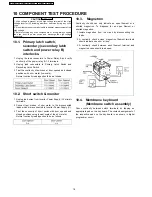
Page 18: ... from Inverter Power Supply U primary terminals 2 Connect test probes of ohm meter to the disconnected leads which were connected to Inverter Power Supply U 3 Test the continuity of short switch with door opened and closed positions using lowest scale of the ohm meter Normal continuity readings should be as follows 10 3 Magnetron Continuity checks can only indicate an open filament or a shorted ma...

Page 19: ...minute and press start a After approximately 23 seconds oven stops b During oven operation input current is approximately 0 5 to 1A If both a and b are OK please proceed to test 2 INPUT AMPERE FAILURE CODE Unplug CN703 0 5 to 1A Oven stops in 23 seconds after started Test2 Continued from Test 1 1 Unplug 3 pin connector CN701 CN703 remains unplug 2 Set oven at High power for 1 minute and start a Af...

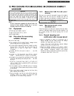
Page 20: ...y following the components test procedures 11 2 Measurement of microwave output The output power of the magnetron can be determined by performing IEC standard test procedures However due to the complexity of IEC test procedures it is recommended to test the magnetron using the simple method outlined below Necessary Equipment 1 liter beaker Glass thermometer Wrist watch or stopwatch NOTE Check the ...

Page 21: ...0cc and place in the center of the oven 2 Set the radiation monitor to 2450MHz and use it following the manufacturer s recommended test procedure to assure correct results 3 When measuring the leakage always use the 2 inch 5cm spacer supplied with the probe 4 Tap the start pad or set the timer and with the magnetron oscillating measure the leakage by holding the probe perpendicular to the surface ...

Page 22: ...12 4 At least once a year have the radiation monitor checked for calibration by its manufacturer 22 NN S262SF NN S262BF NN S262WF NN S252BF NN S252WF ...

Page 23: ...nput Program 1 2 Key input is not insequence Open or loose connection of membrane key pad to DPC Flat cable Refer to operation procedure 3 Shorted or open membrane key board 4 Defective DPC Refer to DPC troubleshooting 4 Fan motor turn on when oven is plugged in with door closed 3 Misadjustment or loose wiring of secondary latch switch Adjust door and latch switches 4 Defective secondary latch swi...

Page 24: ...h tester for the presence of layer short circuit check primary coil resistance If any abnormal condition is detected replace the defective parts No key input 1 Membrane switch continuity Abnormal Membrane switch Normal IC 1 No beep sound 1 IC 1 pin 8 voltage Abnormal IC 1 Normal BUZZER Q224 Power relay A RY 1 does not turn oneven though the program has been setand the start pad is tapped 1 IC 1 pi...

Page 25: ...odes of H97 H98 and H99 First you must program the DPC by pressing Clock Timer Start Power Level Program unit for operation H97 H98 H99 appears in display window a short time after start key is pressed and there is no microwave oscillation Alternate way to troubleshoot oven with AC Ampere meter used H97 H98 H99 appears in display window a short time after start key is pressed and no microwave osci...

Page 26: ...13 3 How to check the semiconductors using an OHM meter 26 NN S262SF NN S262BF NN S262WF NN S252BF NN S252WF ...

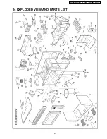
Page 27: ...14 EXPLODED VIEW AND PARTS LIST 27 NN S262SF NN S262BF NN S262WF NN S252BF NN S252WF ...

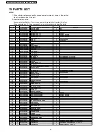
Page 28: ...F42485H00AP FAN CASE C 1 19 F41585H00AP FAN CASE INSTALLATION PLATE 1 20 F42505H00AP SIROCCO FAN C 1 21 F42675H00AP FAN MOTOR B 1 FOR MAGNETRON COOLING 22 F601L5H00AP SENSOR BU 1 S262SF BF WF 23 F40245H00AP EXHAUST GUIDE A 1 24 F44775H00AP EXHAUST GUIDE 1 25 F20025H00AP RACK SUPPORT 4 S262SF BF WF 26 F65855H00AP INVERTER BRACKET 1 28 F62385H00AP WASHER 1 S262SF BF WF 30 F201H5H00AP MAGNET CASE U 2...

Page 29: ...TOR CAPACITOR 1 60 F63264080AP TURNTABLE MOTOR 1 61 F900C5H00AP AC CORD W PLUG 1 APH 61 F900C5H00CP AC CORD W PLUG 1 CPH 62 F90804W00AP CANOE CLIP 1 FOR COVER 63 F101V5H00AP VENT GRILLE U 1 S262SF 63 F101V5H10BAP VENT GRILLE U 1 S262BF S252BF 63 F101V5H10HAP VENT GRILLE U 1 S262WF S252WF 64 F48435H00AP INHALE GUIDE A 1 69 F01725H00AP CAUTION LABEL 1 70 F00565H00AP CAUTION LABEL 1 71 F03345H10AP ME...

Page 30: ...0AP DOOR KEY SPRING 1 D5 F30855H00AP DOOR C 1 D6 F31455H00AP DOOR SCREEN A 1 D7 F02459660AP DHHS LABEL 1 APH D7 F04114180CP DHHS LABEL 1 CPH 17 WIRING MATERIALS Ref No Part No Part Name Description Pcs Set Remarks W1 F030A5H00AP LEAD WIRE HARNESS 1 APH W1 F030A5H00CP LEAD WIRE HARNESS 1 CPH W2 F030E5H00AP H V LEAD WIRE 1 APH W2 F030E5H00CP H V LEAD WIRE 1 CPH W3 F03535H00AP LEAD WIRE HARNESS U 1 3...

Page 31: ... U 1 S252WF CPH E3 F80345H10BAP ESCUTCHEON BASE 1 S262BF S252BF E3 F80345H10HAP ESCUTCHEON BASE 1 S262WF S252WF E4 F80725H10BAP DOOR OPENING BUTTON 1 S262BF S252BF E4 F80725H10HAP DOOR OPENING BUTTON 1 S262WF S252WF E5 F80375950AP OPENING BUTTON SPRING 1 E6 F82565H00AP DOOR OPENING LEVEL 1 E7 F81275H00AP BACK PLATE 1 E8 F00075H00AP NAME PLATE 1 S262SF APH E8 F00075H10BAP NAME PLATE 1 S262BF APH E8...

Page 32: ...G CASE PAPER 1 S262WF CPH P2 F01025H20BCP PACKING CASE PAPER 1 S252BF CPH P2 F01025H20HCP PACKING CASE PAPER 1 S252WF CPH P3 F01045H00AP UPPER FILLER 1 P4 F01055H00AP LOWER FILLER 1 P5 F01065H00AP P E BAG 1 P6 F01075H00AP DOOR SHEET 1 P7 A06015H00AP COOKING TRAY 1 P8 F01175H00AP TRAY PACKING B 1 S262SF BF WF P9 F01485H00AP REINFORCE BRACKET 2 P10 F01085H00AP TRAY PACKING 1 P11 F01925H00AP SHEET 2 ...

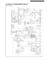
Page 33: ...20 DIGITAL PROGRAMMER CIRCUIT SCHEMATIC DIAGRAM 33 NN S262SF NN S262BF NN S262WF NN S252BF NN S252WF ...

Page 34: ...34 NN S262SF NN S262BF NN S262WF NN S252BF NN S252WF ...

Page 35: ...4EKE CHIP DIDI TRANSISTOR 1 Q25 Q182 Q224 AESC23JKE CHIP DIDI TRANSISTOR 3 Q180 2SD1859TV2Q TRANSISTOR 1 Q581 2SA1037AK TRANSISTOR 1 S262SF BF WF Q40 Q181 Q220 Q225 2SC2412KT146 CHIP TRANSISTOR 4 R311 AERJ06J102R CHIP RESISTOR 1 1KΩ Ω Ω Ω 1 16W 5 R224 R340 R341 R344 R490 R588 AERJ06J103R CHIP RESISTOR 6 10K 1 16W 5 R568 R583 R589 R590 AERJ06J103R CHIP RESISTOR 4 10K 1 16W 5 S262SF BF WF R221 R226 ...

Page 36: ...M RESISTOR 1 150K 1 4W 5 R12 AERDY2TJ331T CARBON FILM RESISTOR 1 330Ω Ω Ω Ω 1 4W 5 R576 R577 R578 R586 AEROY2F3300T RESISTOR 4 330Ω Ω Ω Ω 1 4W 5 VZ490 AEVTZ6TLT103 VARIABLE RESISTOR 1 10KΩ Ω Ω ΩVR RY1 AEGG5G1A18 POWER RELAY 1 RY2 RY3 RY4 RY5 RY6 RY7 AEBJQ1A18 POWER RELAY 6 T10 AETP35K136A LOW VOLTAGE TRANSFORMER 1 ZD12 AESZMTZJ150B ZENER DIODE 1 S262SF BF WF 36 NN S262SF NN S262BF NN S262WF NN S25...

Reviews: