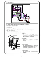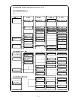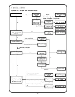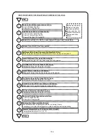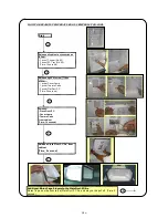
XI. METHODE TO REPAIRING REFRIGERATING UNIT
CONDITION I. NOT COLD
Compressor not run
CONDITION II. COLD LESS
CONDITION III. VERY COLD
Both terminal direct
joining
Compressor run
Compressor not run
Compressor run
Check with Ohm Meter
( Tester )
Change Thermostat
OLP broken
Check with M.Tester
Change O L P
Starting PTC broken
Check with M.Tester
Change Starting PTC
Motor winding burn
Check with M.Tester
Change Compressor
Compressor noise but
not run
Power source broken
(Start Voltage not
enough )
Starting P.T.C. broken
Motor winding
disconnect
Starting Motor burn
Check Starting P.T.C.
Voltage under load
Check with
M.Tester
Check with M.Tester
Repair Power Source
Change PTC Starting
Change Compressor
Change Compressor
Cooling Unit brooken
Gas leakage
Be found gas residu
Repair gas leakage and
re-charge
Gas nothing
Spray with gas
Compressor run but not
compress
Short time
Operation fault
Thermostat broken
Change Thermostat
Compressor running
Long time
Out side Evaporator
Evaporator closed by
frost to more
Evaporator not close by
frost
Very Cold
Touch Defrost button
Cooling Unit broken
Repair at cooling unit
portion
Joint pipe leakage and
clogged
The door have more
gap
Open the door very
long time
Cold Less
Check Cooling Unit
Repair at cooling unit
portion
Adjust the door
Give the direction to
customer
Censor cappilary
Thermostat have more
gap
Thermostat broken
Thermostat not have
voltage
Assembly censor
cappilary Thermostat
Check with M.Tester
Setting end of Censor at
center hole
Change Thermostat
Repair Thermostat
wiring
Check with M.Tester
CHECK
CAUSE
SUSPECT
ANALYSIS
ACTION
-9-
Summary of Contents for NR-B203G-S7
Page 10: ... 9 ...
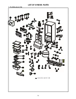
Page 22: ...1 Part Structure 1 2 LIST OF SPARES PARTS INDICATED SAFETY PART 52 90 91 19 ...
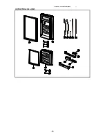
Page 23: ...PMIRF0806022AI 1 2 Part Structure 2 2 20 ...
Page 26: ... 22 ...


